Com express connectors signal description – DFI CD9A3 series User Manual
Page 16
www.dfi .com
Chapter 3 Hardware Installation
16
Chapter 3
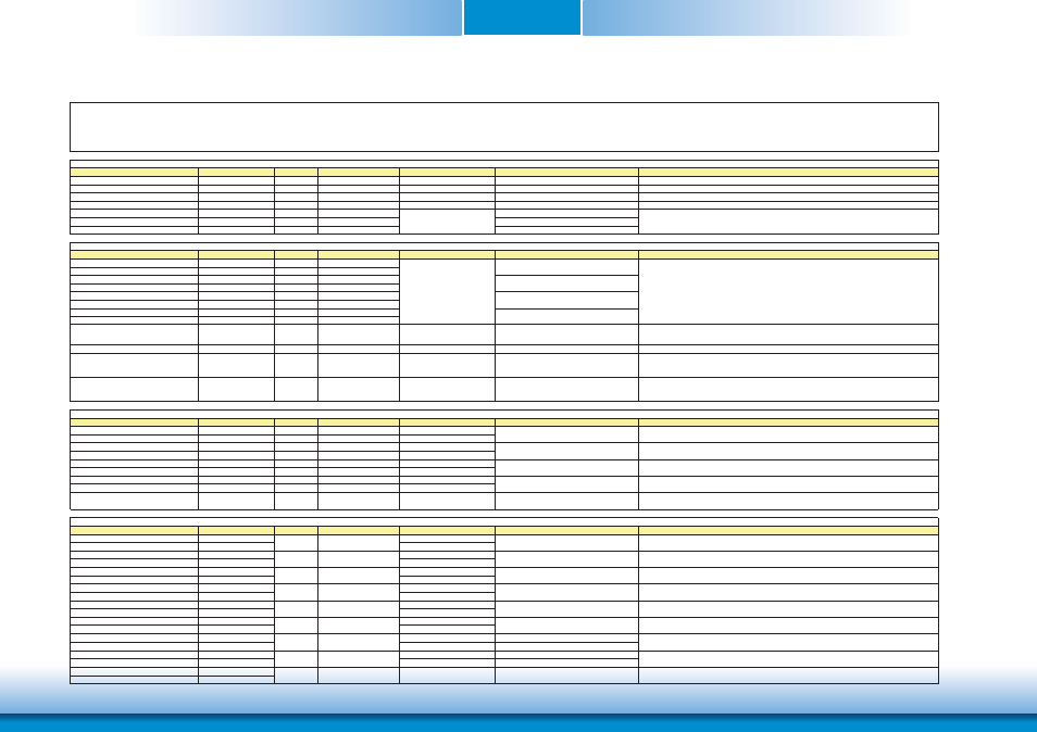
COM Express Connectors Signal Description
Signal
Pin#
Pin Type
Pwr Rail /Tolerance
CD9A3 Series
Carrier Board
Description
AC/HAD_RST#
A30
O CMOS
3.3V Suspend/3.3V
Connect to CODEC pin 11 RESET#
Reset output to CODEC, active low.
AC/HDA_SYNC
A29
O CMOS
3.3V/3.3V
Connect to CODEC pin 10 SYNC
Sample-synchronization signal to the CODEC(s).
AC/HDA_BITCLK
A32
I/O CMOS
3.3V/3.3V
Connect to CODEC pin 6 BIT_CLK
Serial data clock generated by the external CODEC(s).
AC/HDA_SDOUT
A33
O CMOS
3.3V/3.3V
Connect to CODEC pin 5 SDATA_OUT
Serial TDM data output to the CODEC.
AC/HDA_SDIN2
B28
I/O CMOS
3.3V Suspend/3.3V
Connect 33 ƻ in series to CODEC2 pin 8 SDATA_IN
AC/HDA_SDIN1
B29
I/O CMOS
3.3V Suspend/3.3V
Connect 33 ƻ in series to CODEC1 pin 8 SDATA_IN
AC/HDA_SDIN0
B30
I/O CMOS
3.3V Suspend/3.3V
Connect 33 ƻ in series to CODEC0 pin 8 SDATA_IN
Signal
Pin#
Pin Type
Pwr Rail /Tolerance
CD9A3 Series
Carrier Board
Description
GBE0_MDI0+
A13
I/O Analog
3.3V max Suspend
GBE0_MDI0-
A12
I/O Analog
3.3V max Suspend
GBE0_MDI1+
A10
I/O Analog
3.3V max Suspend
GBE0_MDI1-
A9
I/O Analog
3.3V max Suspend
GBE0_MDI2+
A7
I/O Analog
3.3V max Suspend
GBE0_MDI2-
A6
I/O Analog
3.3V max Suspend
GBE0_MDI3+
A3
I/O Analog
3.3V max Suspend
GBE0_MDI3-
A2
I/O Analog
3.3V max Suspend
GBE0_ACT#
B2
OD CMOS
3.3V Suspend/3.3V
Connect to LED and recommend current limit
resistor 150ȟ to 3.3VSB
Gigabit Ethernet Controller 0 activity indicator, active low.
GBE0_LINK#
A8
OD CMOS
3.3V Suspend/3.3V
NC
Gigabit Ethernet Controller 0 link indicator, active low.
GBE0_LINK100#
A4
OD CMOS
3.3V Suspend/3.3V
Connect to LED and recommend current limit
resistor 150ȟ to 3.3VSB
Gigabit Ethernet Controller 0 100 Mbit / sec link indicator, active low.
GBE0_LINK1000#
A5
OD CMOS
3.3V Suspend/3.3V
Connect to LED and recommend current limit
resistor 150ȟ to 3.3VSB
Gigabit Ethernet Controller 0 1000 Mbit / sec link indicator, active low.
Signal
Pin#
Pin Type
Pwr Rail /Tolerance
CD9A3 Series
Carrier Board
Description
SATA0_TX+
A16
O SATA
AC coupled on Module
AC Coupling capacitor
SATA0_TX-
A17
O SATA
AC coupled on Module
AC Coupling capacitor
SATA0_RX+
A19
I SATA
AC coupled on Module
AC Coupling capacitor
SATA0_RX-
A20
I SATA
AC coupled on Module
AC Coupling capacitor
SATA1_TX+
B16
O SATA
AC coupled on Module
AC Coupling capacitor
SATA1_TX-
B17
O SATA
AC coupled on Module
AC Coupling capacitor
SATA1_RX+
B19
I SATA
AC coupled on Module
AC Coupling capacitor
SATA1_RX-
B20
I SATA
AC coupled on Module
AC Coupling capacitor
ATA_ACT#
A28
I/O CMOS
3.3V / 3.3V
PU 10K to 3.3V
Connect to LED and recommend current limit
resistor 220ƻ to 3.3V
ATA (parallel and serial) or SAS activity indicator, active low.
Signal
Pin#
Pin Type
Pwr Rail /Tolerance
CD9A3 Series
Carrier Board
Description
PCIE_TX0+
A68
AC Coupling capacitor
PCIE_TX0-
A69
AC Coupling capacitor
PCIE_RX0+
B68
PCIE_RX0-
B69
PCIE_TX1+
A64
AC Coupling capacitor
PCIE_TX1-
A65
AC Coupling capacitor
PCIE_RX1+
B64
PCIE_RX1-
B65
PCIE_TX2+
A61
AC Coupling capacitor
PCIE_TX2-
A62
AC Coupling capacitor
PCIE_RX2+
B61
PCIE_RX2-
B62
PCIE_TX3+
A58
NA
NA
PCIE_TX3-
A59
NA
NA
PCIE_RX3+
B58
NA
NA
PCIE_RX3-
B59
NA
NA
PCIE0_CK_REF+
A88
PCIE0_CK_REF-
A89
ȟ
ȟ
ȟ
ȟ
Device - Connect AC Coupling cap 0.1uF
Slot - Connect to PCIE Conn pin
Connect to PCIE device or slot
Device - Connect AC Coupling cap 0.1uF
Slot - Connect to PCIE Conn pin
Connect to PCIE device or slot
Connect to PCIE device, PCIe CLK Buffer or slot
Pin Types
I Input to the Module
O Output from the Module
I/O Bi-directional input / output signal
OD Open drain output
Connect to Magnetics Module MDI0+/-
Connect to Magnetics Module MDI1+/-
Connect to Magnetics Module MDI2+/-
Connect to Magnetics Module MDI3+/-
Connect to SATA0 Conn RX pin
Connect to SATA1 Conn TX pin
O PCIE
AC coupled on Module
PCI Express Differential Transmit Pairs 2
I PCIE
AC coupled off Module
PCI Express Differential Receive Pairs 1
O PCIE
PCIE
Reference clock output for all PCI Express and PCI Express Graphics lanes.
I PCIE
AC coupled off Module
PCI Express Differential Receive Pairs 3 (NA for CD9A3)
O PCIE
AC coupled on Module
PCI Express Differential Transmit Pairs 3 (NA for CD9A3)
I PCIE
AC coupled off Module
PCI Express Differential Receive Pairs 2
Device - Connect AC Coupling cap 0.1uF
Slot - Connect to PCIE Conn pin
AC97/HDA Signals Descriptions
Serial TDM data inputs from up to 3 CODECs.
Gigabit Ethernet Signals Descriptions
Gigabit Ethernet Controller 0: Media Dependent Interface Differential
Pairs 0,1,2,3. The MDI can operate in 1000, 100 and 10 Mbit / sec
modes. Some pairs are unused in some modes, per the following:
1000BASE-T 100BASE-TX 10BASE-T
MDI[0]+/- B1_DA+/- TX+/- TX+/-
MDI[1]+/- B1_DB+/- RX+/- RX+/-
MDI[2]+/- B1_DC+/-
MDI[3]+/- B1_DD+/-
Serial ATA or SAS Channel 1 receive differential pair.
SATA Signals Descriptions
O PCIE
AC coupled on Module
PCI Express Differential Transmit Pairs 1
PCI Express Lanes Signals Descriptions
Serial ATA or SAS Channel 0 transmit differential pair.
Serial ATA or SAS Channel 0 receive differential pair.
O PCIE
AC coupled on Module
PCI Express Differential Transmit Pairs 0
Serial ATA or SAS Channel 1 transmit differential pair.
I PCIE
AC coupled off Module
PCI Express Differential Receive Pairs 0
Connect to SATA1 Conn RX pin
Connect to SATA0 Conn TX pin
Connect to PCIE device or slot