Com express connectors signal description – DFI CR908-B User Manual
Page 16
www.dfi .com
Chapter 3 Hardware Installation
16
Chapter 3
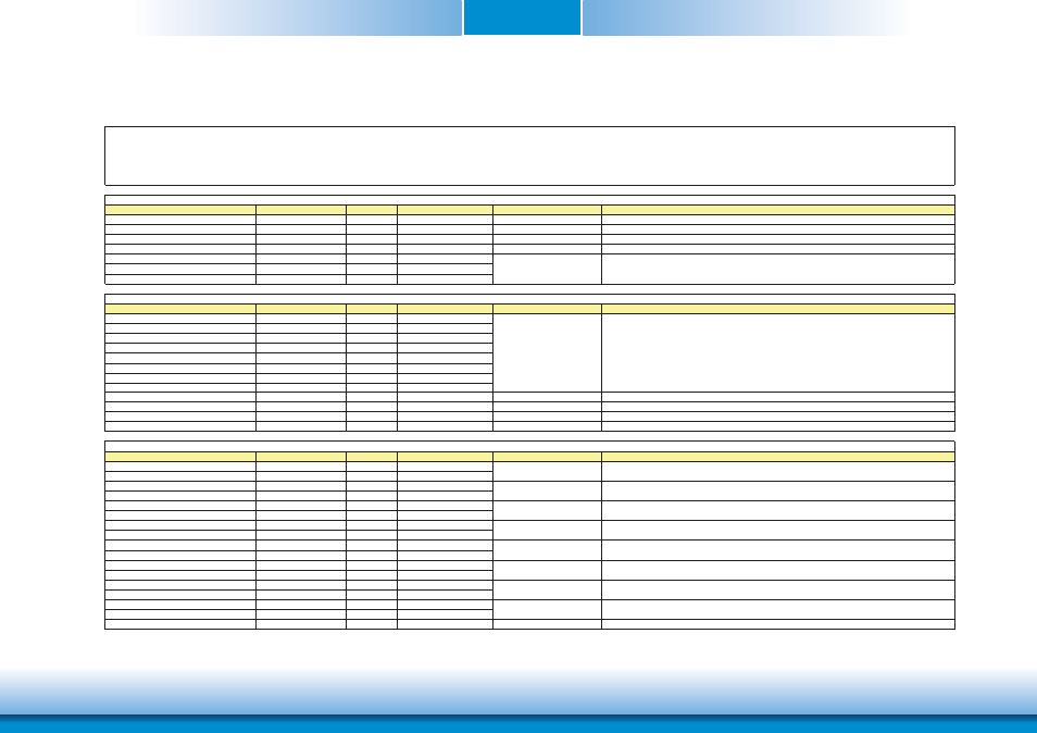
COM Express Connectors Signal Description
Signal
Pin#
Pin Type
Pwr Rail /Tolerance
PU/PD
Description
AC/HAD_RST#
A30
O CMOS
3.3V Suspend/3.3V
Reset output to CODEC, active low.
AC/HDA_SYNC
A29
O CMOS
3.3V/3.3V
PU 1K to 3.3VSB
Sample-synchronization signal to the CODEC(s).
AC/HDA_BITCLK
A32
I/O CMOS
3.3V/3.3V
Serial data clock generated by the external CODEC(s).
AC/HDA_SDOUT
A33
O CMOS
3.3V/3.3V
Serial TDM data output to the CODEC.
AC/HDA_SDIN2
B28
I/O CMOS
3.3V Suspend/3.3V
AC/HDA_SDIN1
B29
I/O CMOS
3.3V Suspend/3.3V
AC/HDA_SDIN0
B30
I/O CMOS
3.3V Suspend/3.3V
Signal
Pin#
Pin Type
Pwr Rail /Tolerance
PU/PD
Description
GBE0_MDI0+
A13
I/O Analog
3.3V max Suspend
GBE0_MDI0-
A12
I/O Analog
3.3V max Suspend
GBE0_MDI1+
A10
I/O Analog
3.3V max Suspend
GBE0_MDI1-
A9
I/O Analog
3.3V max Suspend
GBE0_MDI2+
A7
I/O Analog
3.3V max Suspend
GBE0_MDI2-
A6
I/O Analog
3.3V max Suspend
GBE0_MDI3+
A3
I/O Analog
3.3V max Suspend
GBE0_MDI3-
A2
I/O Analog
3.3V max Suspend
GBE0_ACT#
B2
OD CMOS
3.3V Suspend/3.3V
Gigabit Ethernet Controller 0 activity indicator, active low.
GBE0_LINK#
A8
OD CMOS
3.3V Suspend/3.3V
Gigabit Ethernet Controller 0 link indicator, active low.
GBE0_LINK100#
A4
OD CMOS
3.3V Suspend/3.3V
Gigabit Ethernet Controller 0 100 Mbit / sec link indicator, active low.
GBE0_LINK1000#
A5
OD CMOS
3.3V Suspend/3.3V
Gigabit Ethernet Controller 0 1000 Mbit / sec link indicator, active low.
Signal
Pin#
Pin Type
Pwr Rail /Tolerance
PU/PD
Description
SATA0_TX+
A16
O SATA
AC coupled on Module
SATA0_TX-
A17
O SATA
AC coupled on Module
SATA0_RX+
A19
I SATA
AC coupled on Module
SATA0_RX-
A20
I SATA
AC coupled on Module
SATA1_TX+
B16
O SATA
AC coupled on Module
SATA1_TX-
B17
O SATA
AC coupled on Module
SATA1_RX+
B19
I SATA
AC coupled on Module
SATA1_RX-
B20
I SATA
AC coupled on Module
SATA2_TX+
A22
O SATA
AC coupled on Module
SATA2_TX-
A23
O SATA
AC coupled on Module
SATA2_RX+
A25
I SATA
AC coupled on Module
SATA2_RX-
A26
I SATA
AC coupled on Module
SATA3_TX+
B22
O SATA
AC coupled on Module
SATA3_TX-
B23
O SATA
AC coupled on Module
SATA3_RX+
B25
I SATA
AC coupled on Module
SATA3_RX-
B26
I SATA
AC coupled on Module
ATA_ACT#
A28
I/O CMOS
3.3V / 3.3V
PU 10K to 3.3V
ATA (parallel and serial) or SAS activity indicator, active low.
Pin Types
I Input to the Module
O Output from the Module
I/O Bi-directional input / output signal
OD Open drain output
Serial ATA or SAS Channel 0 transmit differential pair.
Serial ATA or SAS Channel 0 receive differential pair.
Serial ATA or SAS Channel 1 transmit differential pair.
Serial ATA or SAS Channel 3 transmit differential pair.
Serial ATA or SAS Channel 3 receive differential pair.
Serial ATA or SAS Channel 2 receive differential pair.
AC97/HDA Signals Descriptions
Serial TDM data inputs from up to 3 CODECs.
Gigabit Ethernet Signals Descriptions
Serial ATA or SAS Channel 2 transmit differential pair.
Gigabit Ethernet Controller 0: Media Dependent Interface Differential
Pairs 0,1,2,3. The MDI can operate in 1000, 100 and 10 Mbit / sec
modes. Some pairs are unused in some modes, per the following:
1000BASE-T 100BASE-TX 10BASE-T
MDI[0]+/- B1_DA+/- TX+/- TX+/-
MDI[1]+/- B1_DB+/- RX+/- RX+/-
MDI[2]+/- B1_DC+/-
MDI[3]+/- B1_DD+/-
Serial ATA or SAS Channel 1 receive differential pair.
SATA Signals Descriptions