Chapter 3 – DFI CR908-B User Manual
Page 19
www.dfi .com
Chapter 3 Hardware Installation
19
Chapter 3
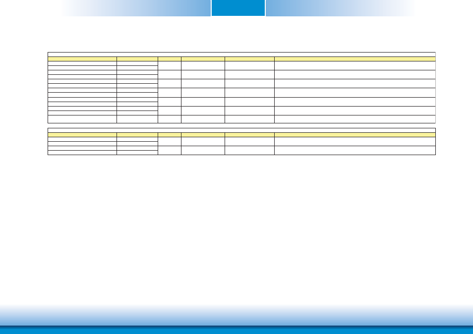
Signal
Pin#
Pin Type
Pwr Rail /Tolerance
PU/PD
Description
PEG Signals Descriptions
PEG_TX13+
D94
PEG_TX13-
D95
PEG_RX13+
C94
PEG_RX13-
C95
PEG_TX14+
D98
PEG_TX14-
D99
PEG_RX14+
C98
PEG_RX14-
C99
PEG_TX15+
D101
PEG_TX15-
D102
PEG_RX15+
C101
PEG_RX15-
C102
PEG_LANE_RV#
D54
I CMOS
3.3V / 3.3V
PCI Express Graphics lane reversal input strap. Pull low on the Carrier
board to reverse lane order.
Signal
Pin#
Pin Type
Pwr Rail /Tolerance
PU/PD
Description
EXCD0_CPPE#
A49
EXCD1_CPPE#
B48
EXCD0_PERST#
A48
EXCD1_PERST#
B47
O CMOS
3.3V /3.3V
PCI ExpressCard: reset, active low, one per card
ExpressCard Signals Descriptions
I CMOS
3.3V /3.3V
PU 10k to 3.3V
PCI ExpressCard: PCI Express capable card request, active low, one per card
I PCIE
AC coupled off Module
PCI Express Graphics receive differential pairs 15
O PCIE
AC coupled on Module
PCI Express Graphics transmit differential pairs 15
I PCIE
AC coupled off Module
PCI Express Graphics receive differential pairs 14
O PCIE
AC coupled on Module
PCI Express Graphics transmit differential pairs 14
I PCIE
AC coupled off Module
PCI Express Graphics receive differential pairs 13
O PCIE
AC coupled on Module
PCI Express Graphics transmit differential pairs 13