DFI CA900-B User Manual
Page 35
Advertising
35
2
Hardware Installation
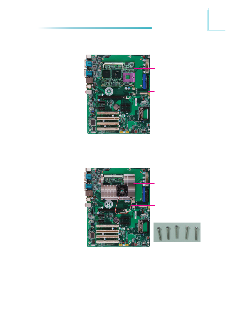
8. Position the heat sink on top of CA900-B with the heat sink’s mounting holes
aligned with CA900-B’s mounting holes. Use the provided long screws to se-
cure the heat sink to the board and then connect the cooling fan’s cable to
the fan connector on CA900-B.
Carrier board
Mounting screws
Fan cable
7. Press CA900-B down firmly until it is completely seated on the COM Express
connectors of the carrier board.
CA900-B
Heat sink
Advertising
This manual is related to the following products: