DFI G5C900-B User Manual
Page 18
Advertising
COM Express Board
18
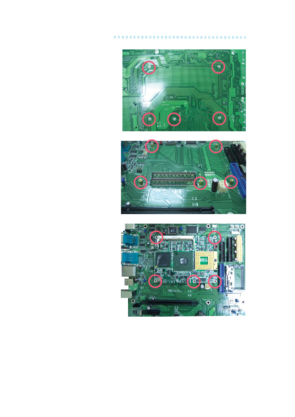
4. The right photo shows
the component side of
the board with the bolts
already fixed in place.
3. The right photo shows
the solder side of the
board with the screws
already fixed in place.
5. Grasping G5C900-B by
its edges, position it on
top of the carrier board
with its mounting holes
aligned with the bolts
on the carrier board.
This will also align the
COM Express connec-
tors of the two boards
to each other.
Press G5C900-B down
firmly until it is com-
pletely seated on the
COM Express connec-
tor s of the carr ier
board.
Advertising
This manual is related to the following products: