Chapter 2 – DFI QB702-B User Manual
Page 14
www.dfi .com
Chapter 2 Hardware Installation
14
Chapter 2
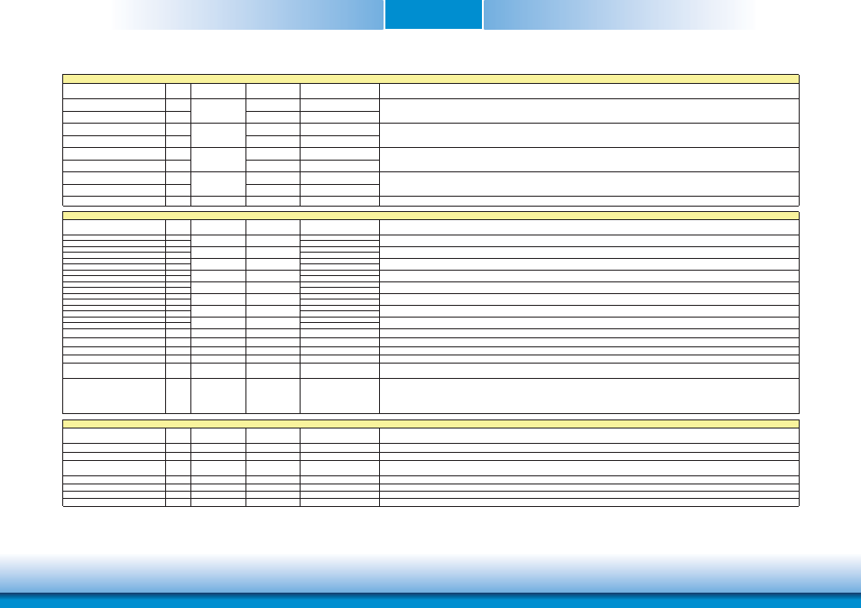
Signal
Pin#
Pin Type
Pwr Rail
/Tolerance
PU/PD (DFI-QB702)
Description
SATA0_RX+
35
AC coupled on
Module
SATA0_RX-
37
AC coupled on
Module
SATA0_TX+
29
AC coupled on
Module
SATA0_TX-
31
AC coupled on
Module
SATA1_RX+
36
AC coupled on
Module
SATA1_RX-
38
AC coupled on
Module
SATA1_TX+
30
AC coupled on
Module
SATA1_TX-
32
AC coupled on
Module
SATA_ACT#
33
O OC 3.3V
3.3V/3.3V
Serial ATA Led. Open collector output pin driven during SATA command activity.
Signal
Pin#
Pin Type
Pwr Rail
/Tolerance
PU/PD (DFI-QB702)
Description
USB_P0+
96
USB_P0-
94
USB_P1+
95
USB_P1-
93
USB_P2+
90
USB_P2-
88
USB_P3+
89
USB_P3-
87
USB_P4+
84
USB_P4-
82
USB_P5+
83
USB_P5-
81
USB_P6+
78
USB_P6-
76
USB_P7+
77
USB_P7-
75
USB_0_1_OC#
86
I CMOS
3.3V Suspend/3.3V
PU 10K to 3.3V Suspend
Over current detect input 1. This pin is used to monitor the USB power over current of the USB Ports 0 and 1.
USB_2_3_OC#
85
I CMOS
3.3V Suspend/3.3V
PU 10K to 3.3V Suspend
Over current detect input 2. This pin is used to monitor the USB power over current of the USB Ports 2 and 3.
USB_4_5_OC#
80
I CMOS
3.3V Suspend/3.3V
PU 10K to 3.3V Suspend
Over current detect input 3. This pin is used to monitor the USB power over current of the USB Ports 4 and 5.
USB_6_7_OC#
79
I CMOS
3.3V Suspend/3.3V
Not support
Over current detect input 4. This pin is used to monitor the USB power over current of the USB Ports 6 and 7.
USB_ID
92
I CMOS
3.3V Suspend/3.3V
PD 10K
USB ID pin.Configures the mode of the USB Port 1. If the signal is detected as being 'high active' the BIOS will automatically configure USB Port 1 as USB Client and
enable USB Client support. This signal should be driven as OC signal by external circuitry.
USB_CC
91
I CMOS
3.3V Suspend/3.3V
PD 10K
USB Client Connect pin.If USB Port 1 is configured for client mode then an externally connected USB host should set this signal to high-active in order to properly make
the connection with the module's internal USB client controller.
If the external USB host is disconnected, this signal should be set to low-active in order to inform the USB client controller that the external host has been
disconnected.
A level shifter/protection circuitry should be implemented on the carrier board for this signal.
Signal
Pin#
Pin Type
Pwr Rail
/Tolerance
PU/PD (DFI-QB702)
Description
SDIO_CD#
43
I/O CMOS
3.3V/3.3V
PU 10K to 3.3V
SDIO Card Detect. This signal indicates when a SDIO/MMC card is present.
SDIO_CLK
42
O CMOS
3.3V/3.3V
SDIO Clock. With each cycle of this signal a one-bit transfer on the command and each data line occurs. This signal has maximum frequency of 48 MHz.
SDIO_CMD
45
I/O OD/PP CMOS
3.3V/3.3V
SDIO Command/Response. This signal is used for card initialization and for command transfers. During initialization mode this signal is open drain. During command
transfer this signal is in push-pull mode.
SDIO_LED
44
O CMOS
3.3V/3.3V
SDIO LED. Used to drive an external LED to indicate when transfers occur on the bus.
SDIO_WP
46
I/O CMOS
3.3V/3.3V
PU 10K to 3.3V
SDIO Write Protect. This signal denotes the state of the write-protect tab on SD cards.
SDIO_PWR#
47
O CMOS
3.3V/3.3V
SDIO Power Enable. This signal is used to enable the power being supplied to a SD/MMC card device.
SDIO_DAT0-7
48-55
I/O PP CMOS
3.3V/3.3V
SDIO Data lines. These signals operate in push-pull mode
Universal Serial Bus Port 3 differential pair.
Universal Serial Bus Port 7 differential pair.
I/O USB
I/O USB
I/O USB
I/O USB
I/O USB
I/O USB
I/O USB
Universal Serial Bus Port 1 differential pair.This port may be optionally used as USB client port.
Universal Serial Bus Port 4 differential pair.
Universal Serial Bus Port 5 differential pair.
Universal Serial Bus Port 6 differential pair.
USB
USB
USB
USB
USB
SDIO Interface Signals
USB
USB
USB
USB Interface Signals
Universal Serial Bus Port 0 differential pair.
I/O USB
Universal Serial Bus Port 2 differential pair.
Serial ATA Interface Signals
I SATA
O SATA
I SATA
O SATA
Serial ATA channel 0, Receive Input differential pair.
Serial ATA channel 1, Receive Input differential pair.
Serial ATA channel 0, Transmit Output differential pair.
Serial ATA channel 1, Transmit Output differential pair.