Mechanical diagram, Chapter 2 mechanical diagram – DFI QB702-B User Manual
Page 9
Advertising
www.dfi .com
Chapter 2 Hardware Installation
9
Chapter 2
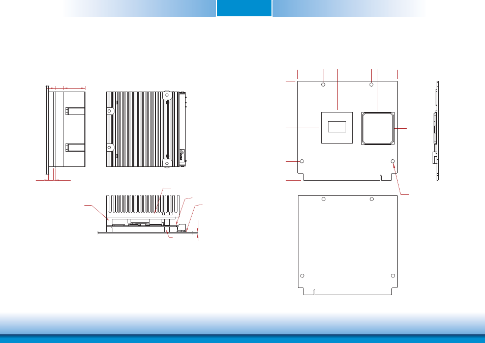
Mechanical Diagram
QB702-B Module with thermal solution
Side View of the Module with thermal solution and Carrier Board
QB702-B Module
00
1.20
8.00
20.20
Heatsink
Heatspreader
1.60
Carrier PCB
Module PCB
Standoff
70.00
0.00
18.00
52.00
27
.7
4
56.48
70.00
0.00
32.86
56.50
33.33
Ø2.50 (*4pcs)
Bottom View
Top View
Advertising