Jumper settings, Chapter 2 – DFI CD951-C2600 User Manual
Page 10
www.dfi .com
10
Chapter 2 Hardware Installation
Chapter 2
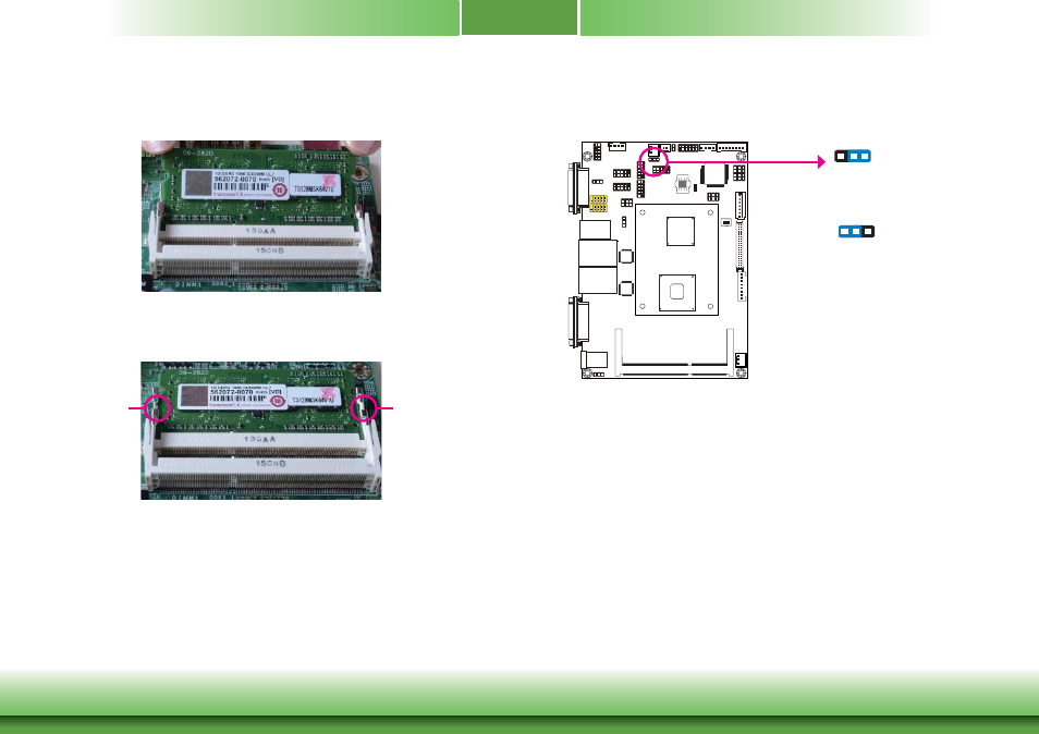
6. Push down the module until the clips at each end of the socket lock into position. You will
hear a distinctive “click”, indicating the module is correctly locked into position.
Clip
5. Grasping the module by its edges, align the module into the socket at an approximately 30
degrees angle. Apply firm even pressure to each end of the module until it slips down into
the socket. The contact fingers on the edge of the module will almost completely disappear
inside the socket.
Clip
Jumper Settings
Clear CMOS
If you encounter the following,
a) CMOS data becomes corrupted.
b) You forgot the supervisor or user password.
you can reconfigure the system with the default values stored in the ROM BIOS.
To load the default values stored in the ROM BIOS, please follow the steps below.
1. Power-off the system and unplug the power cord.
2. Set JP7 pins 2 and 3 to On. Wait for a few seconds and set JP7 back to its default setting,
pins 1 and 2 On.
3. Now plug the power cord and power-on the system.
JP7
2-3 On:
Clear CMOS
1-2 On: Normal
(default)
1
3 2
1
3 2