Chapter 2 – DFI CD951-C2600 User Manual
Page 20
www.dfi .com
20
Chapter 2 Hardware Installation
Chapter 2
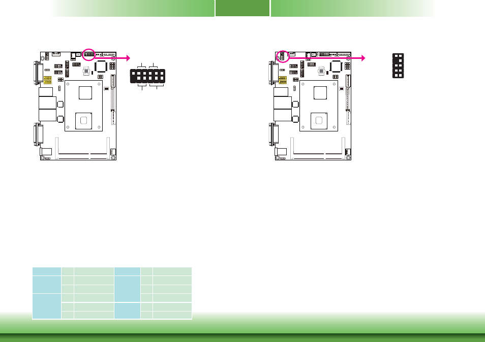
Front Panel Connector
HDD-LED - HDD LED
This LED will light when the hard drive is being accessed.
RESET SW - Reset Switch
This switch allows you to reboot without having to power off the system.
PWR-BTN - Power Switch
This switch is used to power on or off the system.
PWR-LED - Power/Standby LED
When the system’s power is on, this LED will light. When the system is in the S1 (POS - Power
On Suspend) state, it will blink every second. When the system is in the S3 (STR - Suspend To
RAM) state, it will blink every 4 seconds.
HDD-LED
RESET
-S
W
PWR
-LED
PWR
-B
TN
12
11
2
1
Pin Pin Assignment
Pin Pin Assignment
HDD-LED
3
HDD Power
PWR-LED
2
LED Power
5
Signal
4
LED Power
RESET SW
7
Ground
6
Signal
9
RST Signal
PWR-BTN
8
Ground
11 N.C.
10
Signal
Front Audio Connector
1
Mic IN-L
Line OUT-R
GND
GND
NC
Key
2
10
Mic-JD
Line OUT-JD
9
Mic IN-R
Line OUT-L
The front audio connector allows you to connect to the second line-out and mic-in jacks that
are at the front panel of your system.