EM Acoustics HALO bi-amplified line array system User Manual
Page 13
Page 13 of 39
HALO system User Manual
V2.2 August 2010
This section describes setting up of a HALO array similar to that shown above, comprising
HALO-S subwoofers and HALO elements.
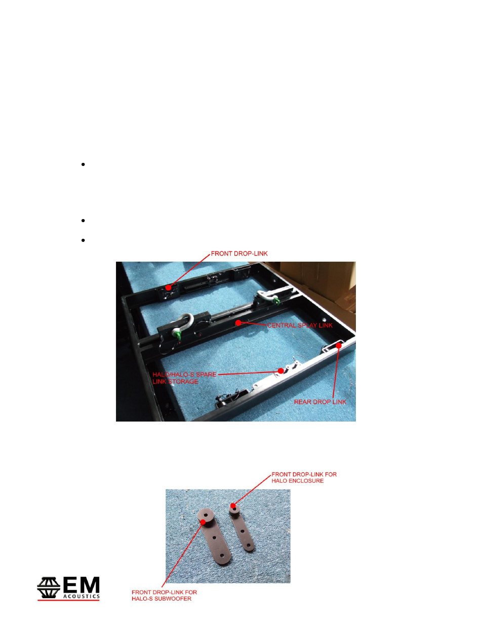
Step One – MFG-HALO grid preparation
The drop links for the MFG-HALO grid are stored inside the chassis of the flying grid for
transport. The first step is to prepare these links ready to fly the system. The MFG-HALO
grid has five link positions:
Front Drop Links – these are removable and are used for flying both HALO-S and
HALO enclosures. Two different sets of front links are provided – larger links for
HALO-S subwoofers and smaller links for HALO enclosures. The alternate links are
stored in recesses on the sides of the MFG grid as shown below.
Rear Drop Links – these are fixed and are only used for flying HALO-S Subwoofers.
Central Splay Link – this is fixed and is only used for flying HALO enclosures.
Firstly, ensure you have the correct front drop links in place to fly your chosen system. In
this example, we are flying a HALO-S subwoofer at the top of the array and as such we
want the larger of the two links as shown in the image below.