EM Acoustics HALO bi-amplified line array system User Manual
Page 25
Page 25 of 39
HALO system User Manual
V2.2 August 2010
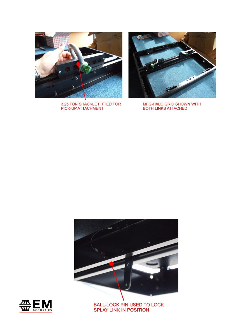
3.25 ton bow shackles can then be used to select the appropriate connection hole in each
pick-up link as shown above.
The second means of securing pick-up points on the MFG-HALO grid is to use the four
holes located front & rear on the grid to attach 3.25 ton bow shackles, and bridle between
them. An example of this procedure is shown in the photo below. These additional points
can also be used to attach secondary safeties to the system.
Ensure with whichever method you use for pick-up, that you have the MFG-HALO grid
facing the right direction – indicated by the “FRONT” arrows on each side of the grid.
The last step prior to attaching your HALO enclosures is to set the desired splay angle for
the first HALO enclosure in the array. For this, you need the central splay link on the
MFG-HALO grid. This link pivots on a bolt and is secured in the transit position by a ball-
lock pin. Release this pin and rotate the link to the desired position – either 0 degrees
(top HALO enclosure is parallel to the grid) or 5 degrees (top enclosure is angled down 5
degrees relative to the SLG grid). Secure in position with the ball-lock pin as shown
below.