EM Acoustics HALO bi-amplified line array system User Manual
Page 16
Page 16 of 39
HALO system User Manual
V2.2 August 2010
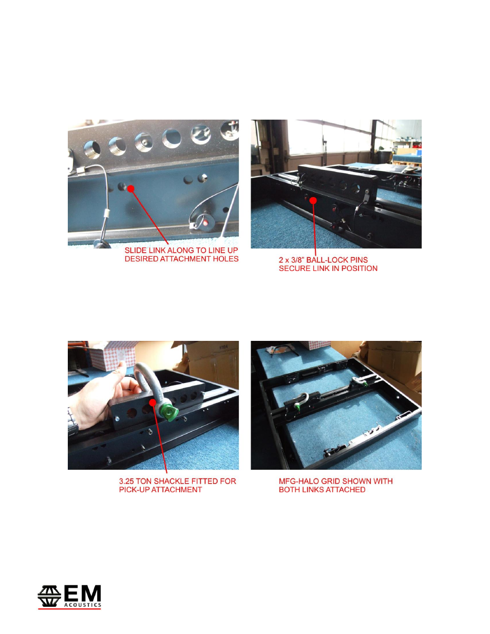
Fit the links into the groove down the central spine on the MFG grid, and slide the link
along to the desired position. The different pairs of holes for the 3/8” pins along the
length of the spine allow for a variety of different positions for the pick-up link, with
complete flexibility. Repeat this process for the second pick-up link.
IMPORTANT NOTE:
Both 3/8” ball-lock pins MUST be secured on each pick-up link being used.
3.25 ton bow shackles can then be used to select the appropriate connection hole in each
pick-up link as shown above.
The second means of securing pick-up points on the MFG-HALO grid is to use the four
holes located front & rear on the grid to attach 3.25 ton bow shackles, and bridle between