EM Acoustics HALO bi-amplified line array system User Manual
Page 19
Page 19 of 39
HALO system User Manual
V2.2 August 2010
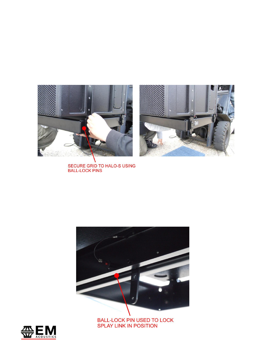
Firstly, ensure you have the SLG-HALO grid in the correct orientation by observing the
“FRONT” labels on the sides of the grid. Release the four ¼” ball-lock pins on the corners
of the grid, to allow the bottom of the HALO-S rigging hardware to mate with the grid.
Offer the grid up to the bottom of the HALO-S (this is possible with one person but is
much easier with two!) and once in position, secure the grid to the bottom of the HALO-S
using the four ball-lock pins secured to the grid itself.
The last step prior to attaching your HALO enclosures is to set the desired splay angle for
the first HALO enclosure in the array. For this, you need the central splay link on the SLG-
HALO grid. This link pivots on a bolt and is secured in the transit position by a ball-lock
pin. Release this pin and rotate the link to the desired position – either 0 degrees (top
HALO enclosure is parallel to the grid) or 5 degrees (top enclosure is angled down 5
degrees relative to the SLG grid). Secure in position with the ball-lock pin as shown
below.