EM Acoustics HALO bi-amplified line array system User Manual
Page 21
Page 21 of 39
HALO system User Manual
V2.2 August 2010
Repeat the above procedure to attach additional HALO enclosures. With the attachment of
each set, ensure the splay links between enclosures are locked in position and set at the
“zero” mark.
Once you have all of your HALO enclosures securely attached, lift the array clear of the
ground to allow you to change inter-enclosure splay angles.
Step 6 – Setting Splay Angles
The HALO rigging system is designed to be extremely easy and intuitive to use, whilst
retaining the highest standards of safety. Inter-enclosure splay can easily be adjusted
using the single rear splay link on each loudspeaker.
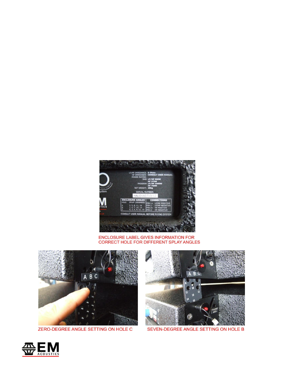
The splay link is clearly marked with numbers on the link itself and “A”, “B”, “C” on the
locking pin holes. Two forms of position indicator are given – on the HALO enclosure label
a description is given as to which angles each hole relates. Additionally, when sliding the
link out of its housing, the first full number shown is the angle at which the link is set at –
see photos below.