EM Acoustics HALO bi-amplified line array system User Manual
Page 24
Page 24 of 39
HALO system User Manual
V2.2 August 2010
IMPORTANT NOTE:
For both front & rear links, the locking ball-lock pin MUST be in position prior to
attempting to fly the system.
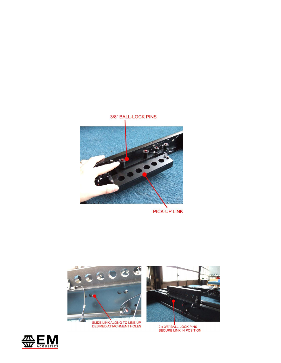
Step Two – Selecting & fitting pick-up links
The MFG-HALO grid provides two means of attaching the grid to your chosen primary
mounting point. The first, and most common is by using the movable pick-up links which
allow for both single point and dual point pick-up. These links are stored for transit on the
side of the MFG grid and are secured in place by two 3/8” ball-lock pins.
Fit the links into the groove down the central spine on the MFG grid, and slide the link
along to the desired position. The different pairs of holes for the 3/8” pins along the
length of the spine allow for a variety of different positions for the pick-up link, with
complete flexibility. Repeat this process for the second pick-up link.
IMPORTANT NOTE:
Both 3/8” ball-lock pins MUST be secured on each pick-up link being used.