EM Acoustics HALO bi-amplified line array system User Manual
Page 17
Page 17 of 39
HALO system User Manual
V2.2 August 2010
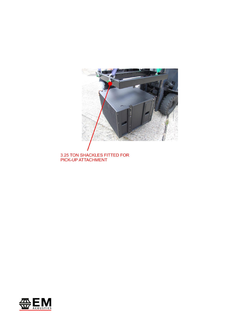
them. An example of this procedure is shown in the photo below. These additional points
can also be used to attach secondary safeties to the system.
Ensure with whichever method you use for pick-up, that you have the MFG-HALO grid
facing the right direction – indicated by the “FRONT” arrows on each side of the grid.
Step 3 – Attaching HALO-S subwoofer enclosures
Once you have your MFG-HALO flying grid prepared, and suspended from your primary
load-bearing point, you are ready to assemble your HALO array. In this example we are
using HALO-S subwoofers, therefore this is the first part of the array to be assembled.
Position your HALO-S enclosure below the grid as shown in the photo above. Release the
four ¼” ball-lock pins on the rigging system, and lower the grid into position – taking care
to ensure that all four drop-links on the MFG-HALO grid locate within the rigging hardware
on the cabinet. Once the grid is in position, secure the grid to the enclosure using the
four ball-lock pins on the HALO-S enclosure.