Flowserve Guardian Sealless Metallic User Manual
Page 32
GUARDIAN USER INSTRUCTIONS ENGLISH 71569212 08-11
Page 32 of 68
flowserve.com
5.4 Direction of rotation
5.4.1
Rotation check, long-coupled pumps
It is absolutely essential that the
rotation of the motor be checked before connecting
the shaft coupling. Incorrect rotation of the pump, for
even a short time, can dislodge and damage the
impeller, casing, shaft and shaft seal. All Guardian G
& H series pumps turn clockwise as viewed from the
motor end. A direction arrow is cast on the front of
the casing as shown in Figure 5-6. Make sure the
motor rotates in the same direction.
Figure 5-6: Direction of rotation arrow
5.4.2
Rotation check, close-coupled pumps
This check will require operating the pump briefly, so
the pump must be filled with liquid. Never run a
centrifugal pump dry. To check rotation, perform the
following steps:
a) Open the suction and discharge valves to allow
the pump to fill with liquid.
b) While watching the motor fan, bump the motor.
The proper direction of rotation for the pump is
clockwise as viewed from the motor end. A
direction arrow cast on the front of the casing as
shown in Figure 5-6.
NEVER DO MAINTENANCE
WORK WHEN THE UNIT IS CONNECTED TO
POWER (Lock Out).
c) If the motor rotates in the wrong direction,
reverse any two of the three leads to the motor (3
phase current). Bump the motor again to ensure
the proper direction of rotation.
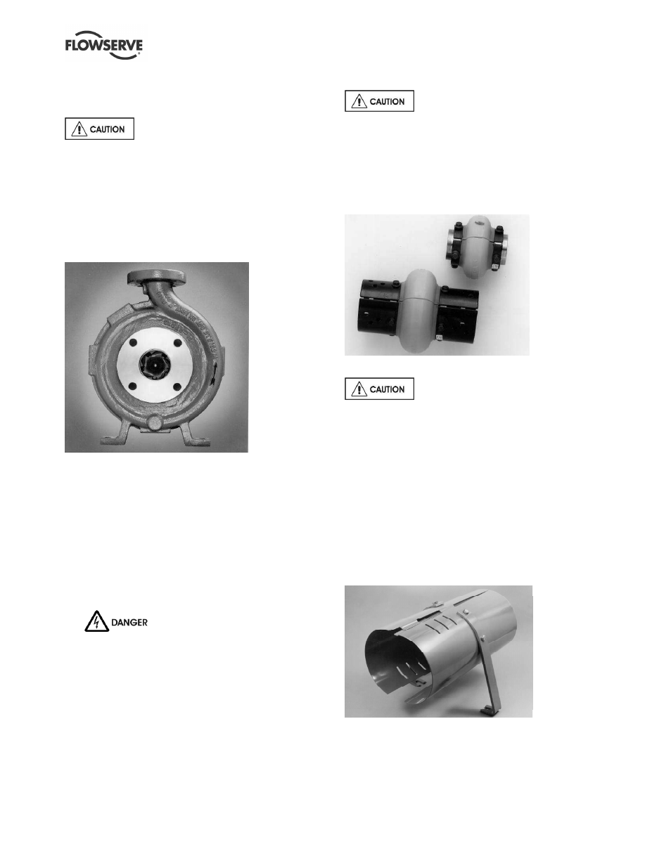
5.4.3
Coupling installation
The coupling (Figure 5-7) should be
installed as advised by the coupling manufacturer.
Pumps are shipped without the spacer installed. If
the spacer has been installed to facilitate alignment,
then it must be removed prior to checking rotation.
Remove all protective material from the coupling and
shaft before installing the coupling.
Figure 5-7: Coupling
5.5 Guarding
Power must never be applied to the
driver when the coupling guard is not installed.
5.5.1
Clam shell guard - standard
The standard coupling guard for all Guardian G & H
series pumps is the “clam shell” design and is shown
in Figure 5-8. It is hinged at the top and it can be
removed by loosening one of the foot bolts and
sliding the support leg out from under the cap screw
(note that the foot is slotted). The leg can then be
rotated upward and half of the guard can be
disengaged (unhinged) from the other. Note that only
one side of the guard needs to be removed. To
reassemble simply reverse the above procedure.
Figure 5-8 Clamshell coupling guard