Flowserve Guardian Sealless Metallic User Manual
Page 40
GUARDIAN USER INSTRUCTIONS ENGLISH 71569212 08-11
Page 40 of 68
flowserve.com
In the event the pump assembly is lodged in the
casing, two jackscrew locations 180 degrees
apart are provided on the adapter [1340]. Inspect
the casing [1100] and the face of the bearing
holder for wear, corrosion, or defects. Remove
the bearing holder/casing gasket [4590.1]. It is
recommended that all O-rings and gaskets be
replaced each time the pump is disassembled.
f) The entire pump without the casing [1100] can
now be moved to the repair shop.
6.7.2.2
Close-coupled Guardian G & H series
pumps
Figure 6-5: Removing entire pump less casing
a) Drain and flush the pump. The Guardian
Magnetic Drive pump is designed to handle
corrosive, toxic, and hazardous process fluids
and may need to be decontaminated prior to any
disassembly.
b) Remove the motor/outer magnet assembly by
following the steps outlined in Section 6.7.1.2.
c) All maintenance can be performed without
removing the casing from the piping. To remove
the pump assembly from the casing, remove all
casing fastener nuts [6580] from the
casing/adapter fasteners [6572].
d) Remove the capscrew holding the lantern foot to
the baseplate (if applicable).
e) Move the pump assembly back from the casing
and rotate the unit out of the casing. (Figure 6-5.)
In the event the pump assembly is lodged in the
casing, two jackscrew locations 180 º apart are
provided on the adapter [1340].
f) Inspect the casing [1100] and the face of the
bearing holder [3830] for wear, corrosion, or
defects. Remove the bearing holder/casing
gasket [4590.1]. It is recommended that all o-
rings and gaskets be replaced each time the
pump is disassembled.
g) The entire pump without the casing [1100] can
now be moved to the repair shop.
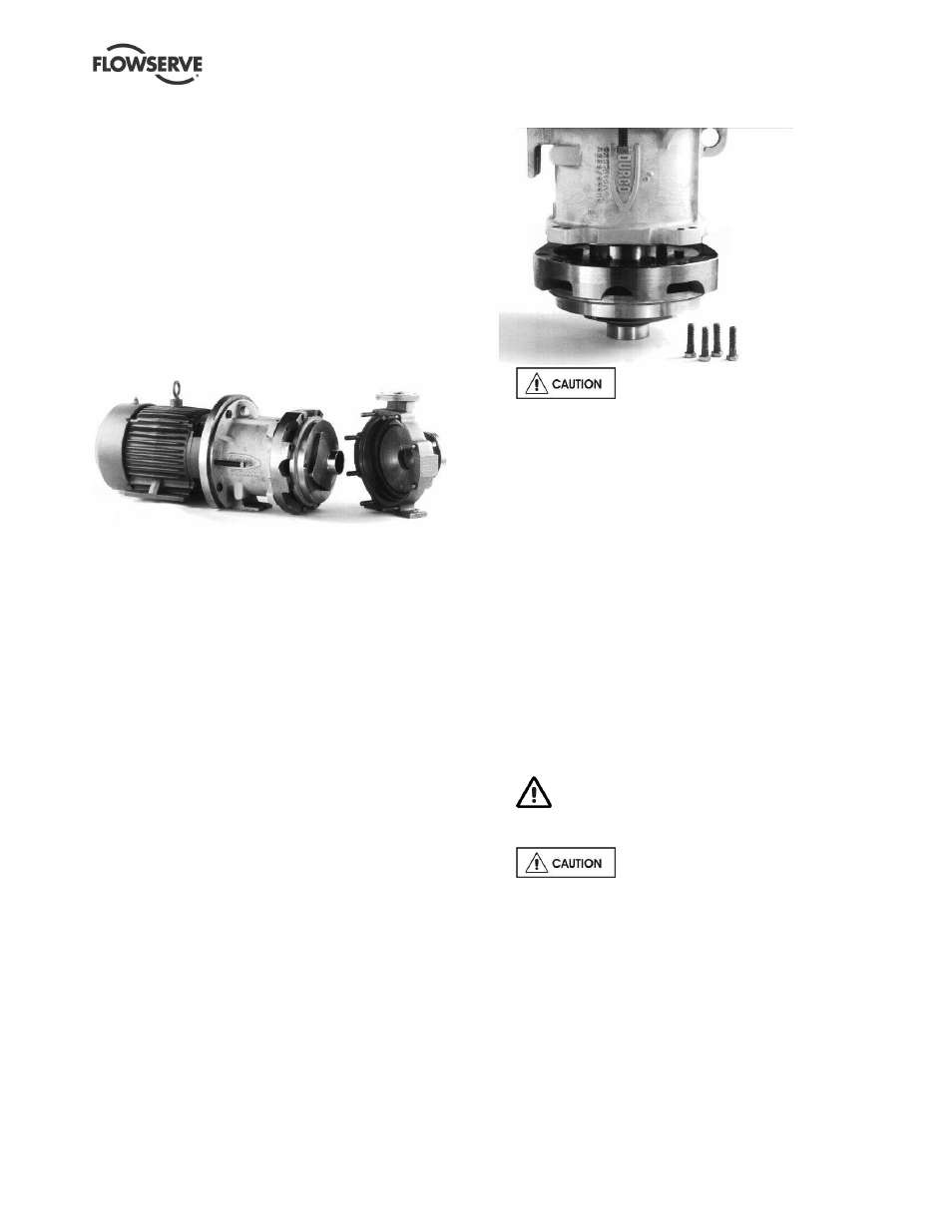
h) To remove the lantern [3132] from the wet end,
orient the back pullout assembly vertically on the
impeller. (Figure 6-6.) Remove the four (4)
lantern/adapter fasteners [6570.5]. Remove the
lantern [3132] by lifting it straight up from the
adapter [1340].
Figure 6-6: Lantern removal
The lantern [3132] is manufactured
from ductile cast iron and may attach to the
containment shell [224] upon removal due to
attraction of the inner magnet assembly.
i)
The entire pump without the casing [1100] can
now be moved to the repair shop.
6.7.3
Detaching the wet end from the power end
At this point, it may be necessary to detach some of
the instrumentation.
a) To remove the power end from the wet end, remove
the four (4) bearing housing/adapter fasteners
[6570.5]. (Figures 6-3A & B.) The magnetic
coupling will remain connected due to the magnetic
forces.
b) Screw the four (4) square head jackbolts [6575]
in the bearing housing [3200] through the
threaded holes until each comes into contact with
a recessed hole in the adapter [1340]. For close
coupled pumps, there are only two (2) jackbolts
[6575]. Continue to screw all jackbolts in evenly
to detach the wet end from the power end.
Do not attempt to remove the power end
from the wet end by any other method. The
magnetic force can cause severe personal injury.
Be sure to separate the inner and
outer magnet assemblies evenly. Cocking of the two
can result in serious damage to the magnets and/or
containment shell. It is best to alternately give each
bolt a turn to ensure proper and even separation.
6.7.4
Disassembling the wet end
Handle the journal and bushing materials with care.
These parts are easily chipped and damaged.
a) Remove the six (6) retainer ring/containment
shell fasteners [6570.6]. Remove the retainer
ring [228]. In case the retainer ring [228] is
lodged in place, two jackscrew locations are
provided to aid in removal. (Figure 6-7.)