Flowserve Guardian Sealless Metallic User Manual
Page 46
GUARDIAN USER INSTRUCTIONS ENGLISH 71569212 08-11
Page 46 of 68
flowserve.com
6.8.4.2
Diameter tolerance, outside diameter
In order to ensure proper fit between bearings and
the bearing housing, verify that the OD on both the IB
and OB bearings are consistently within the
minimum/maximum values shown in Figure 6-25. A
micrometer should be used to check these outside
diameter (OD) dimensions on the bearings.
Figure 6-25
Group 1
Group 2
Bearing
79.992/79.987
(3.1493/3.1491)
110.000/109.985
(4.3307/4.3301)
Housing
80.020/80.005
(3.1504/3.1498)
110.023/110.007
(4.3316/4.3310)
IB and OB
bearing/
housing
mm (in.)
Fit
0.033L/0.013L
(0.0013L/0.0005L)
0.038L/0.008L
(0.0015L/0.0003L)
6.8.5
Impeller balancing
Shaft whip is deflection where the centerline of the
impeller is moving around the true axis of the pump.
It is not caused by hydraulic force but rather by an
imbalance with the rotating element. Shaft whip can
be very hard on the wetted bearings due to the
resulting vibration imparted into the pump. To
minimize shaft whip it is imperative that the impeller is
balanced.
All impellers manufactured by Flowserve are
balanced after they are trimmed. If for any reason, a
customer trims an impeller, it must be re-balanced.
The maximum values of acceptable unbalance are:
•
1 500 r/min: 40 g
·
mm/kg
(1 800 r/min: 0.021 oz-in/lb) of mass.
•
2 900 rpm: 20 g
·
mm/kg
(3 600 rpm: 0.011 oz-in/lb) of mass.
Flowserve performs a single plane spin balance on all
Guardian impellers. All balancing is performed to the
ISO 1940 Grade 6.3 tolerance criteria.
6.8.6
Bearing housing
Prior to installing the shaft into the bearing housing,
check the following parameters.
6.8.6.1
Diameter/tolerance, at bearing surface
In order to ensure proper fit between the bearing
housing and the bearings, verify that the ID of both
the IB and OB bearing surfaces are consistently
within the minimum/maximum values shown in Figure
6-25. An inside caliper should be used to check
these ID dimensions in the bearing housing.
6.8.6.2
Alignment
Misalignment of the pump and motor shafts can
cause the following problems:
•
Failure of the motor and/or pump bearings
•
Failure of the coupling
•
Excessive vibration/noise
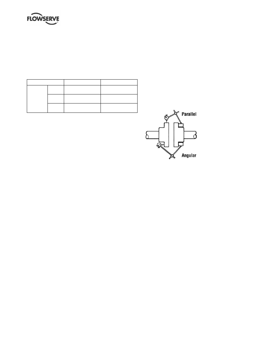
The schematics below show the technique for a typical
rim and face alignment using a dial indicator. It is
important that this alignment be done after the flanges
are loaded, and at typical operating temperatures. If
proper alignment cannot be maintained a stilt/spring
mounting should be considered.
Alignment
Many companies today are using laser alignment
which is a more sophisticated and accurate
technique. With this method a laser and sensor
measure misalignment. This is fed to a computer
with a graphic display that shows the required
adjustment for each of the motor feet.
See section 4.8
for recommended final shaft
alignment limits.
6.8.6.3
Vibration analysis
Vibration analysis is a type of condition monitoring
where a pump’s vibration “signature” is monitored on
a regular, periodic basis. The primary goal of
vibration analysis is extension on MTBPM. By using
this tool Flowserve can often determine not only the
existence of a problem before it becomes serious, but
also the root cause and possible solution.
Modern vibration analysis equipment not only detects
if a vibration problem exists, but can also suggest the
cause of the problem. On a centrifugal pump, these
causes can include the following: unbalance,
misalignment, defective bearings, resonance,
hydraulic forces, cavitation and recirculation. Once
identified, the problem can be corrected, leading to
increased MTBPM for the pump.
Flowserve does not make vibration analysis equipment,
however Flowserve strongly urges customers to work
with an equipment supplier or consultant to establish an
on-going vibration analysis program.