Flowserve Guardian Sealless Metallic User Manual
Page 51
GUARDIAN USER INSTRUCTIONS ENGLISH 71569212 08-11
Page 51 of 68
flowserve.com
Figure 6-35: Shaft cap
Group 1. To tighten the pump shaft cap, place
one wrench on the flats on the back of the inner
magnet and use a torque wrench on the pump
shaft cap.
Group 2 (JG/JH-MG/MH couplings). To tighten
the pump shaft cap, place one wrench on the
flats on the back of the inner magnet and use a
torque wrench on the pump shaft cap.
Group 2 (NG/NH-QG/QH couplings). To tighten
the pump shaft cap, place an adjustable spanner
wrench in the two 5 mm (3/16 in.) diameter holes
on the back of the magnet and use a torque
wrench on the pump shaft cap.
o) Slide the pump shaft/inner magnet assembly
through the bushings CAREFULLY and
SLOWLY. (Figure 6-36.)
Figure 6-36 Inner magnet/shaft assembly
installation
Group 1. Temporarily place shims [3126.2] on
the impeller side of the thrust collar [3610].
(Figure 6-37.) Shims are used to adjust the
impeller clearance. Adjustment will be completed
in Section 6.9.4.
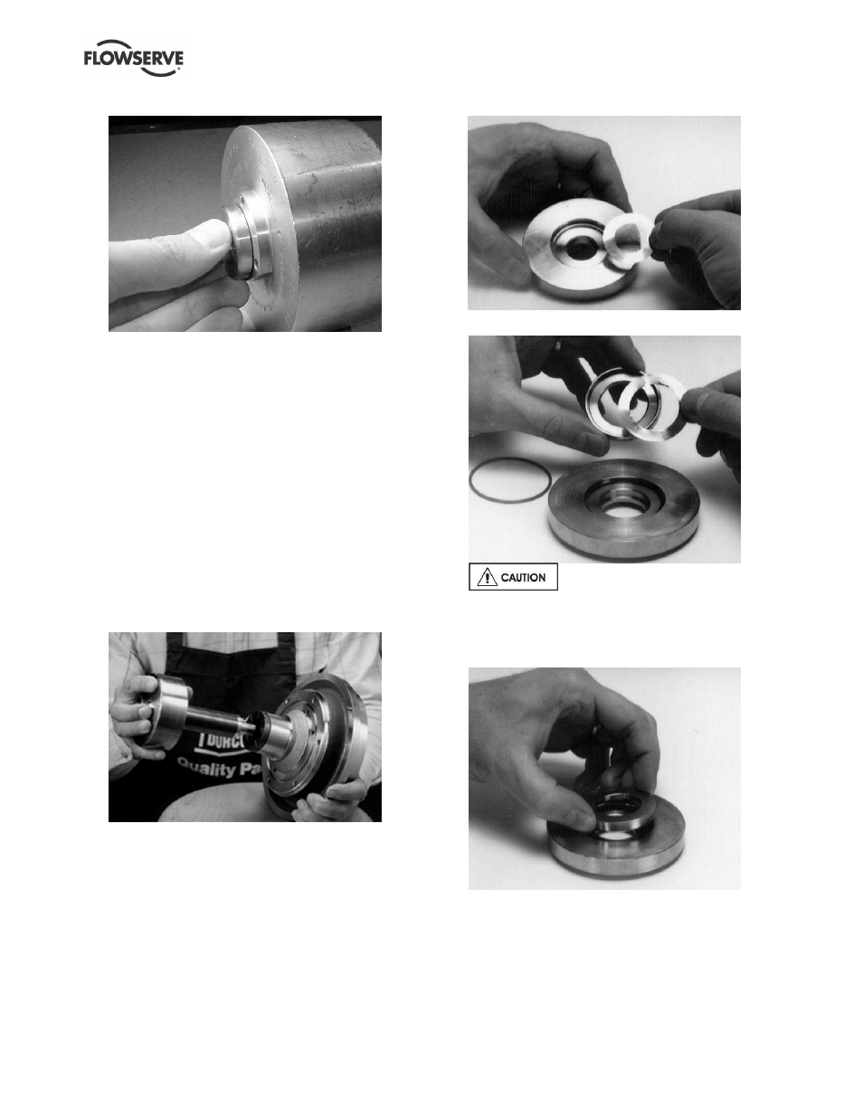
Group 2. On Group 2 pumps, the shims are
sandwiched between the thrust collar [3610] and
thrust collar ring [207]. Place the shims into the
counterbore on the thrust collar ring [207] and hold
them in place with lubricant. (Figure 6-38.) Place
the assembly into the thrust collar. (Figure 6-39.)
Figure 6-37: Group 1 thrust collar with shims
Figure 6-38: Group 2 Thrust Ring with Shims
Make sure the shims sit flat
against the flat surface in the collar ring for Group
2. If they do not sit flat, the impeller may deform
them during the next assembly step.
Figure 6-39 Group 2 Thrust collar/ring
p) Install the inboard thrust journal [211] into the
thrust collar [3610] (using an appropriate
lubricant to hold it in place). (Figure 6-40.) Place
the thrust collar into the bearing holder [3830] so
the thrust journal sits flat on the grooved portion
of the T-shaped bushing [212]. (Figure 6-41.)