Operation – Flowserve OR 52-5 User Manual
Page 29
29
Operation
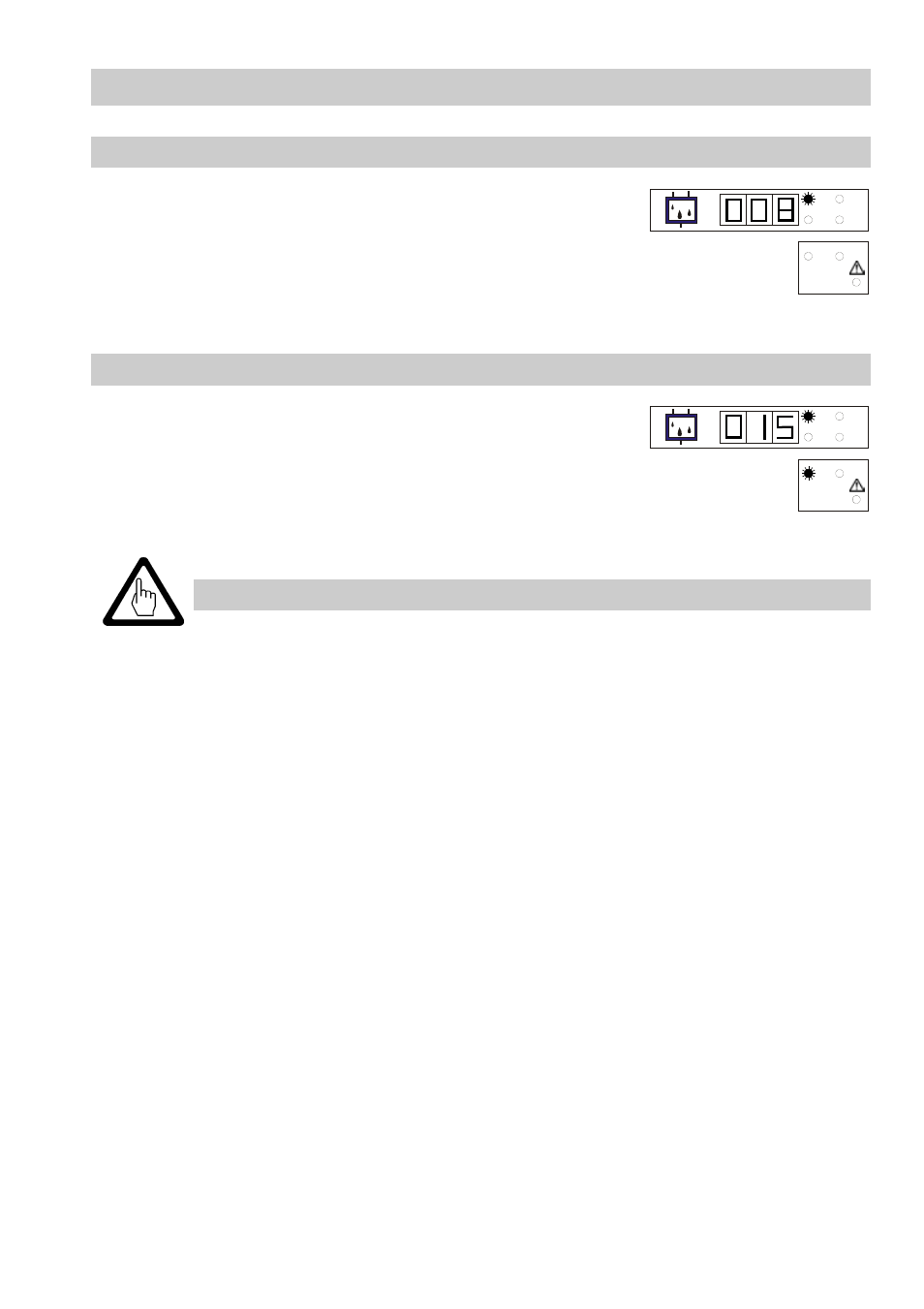
Start
Apply power.
The 7-segment display shows briefly the version number
of the software.
Then the indicator counts until the actual value is
reached.
The LED ppm is illuminated.
Alarm 1 and 2
When the limit value for alarm 1 or 2 is exceeded the
adjusted time delay is activated. The LED alarm 1 or
LED alarm 2 is flashing.
After the time delay has elapsed LED alarm 1 or LED
alarm 2 will light up.
The relay contact for alarm 1 or 2 opens.
ALARM
1
2
ppm
sec
cal
0
OIL
ALARM
1
2
ppm
sec
cal
0
OIL
Note
When the limit values are exceeded the measuring transducer will not
interlock automatically. If the installation requires a lockout function, the
latter must be implemented in the sequence circuit (burner protection
circuit). This circuit must comply with the requirements of the DIN VDE
0116 regulations.