6wiring and grounding guidelines, 1 ff command input wiring, 2 grounding screw – Flowserve 3400MD Digital Positioner User Manual
Page 14
Logix 3400MD Digital Positioner FCD LGENIM3404-08-AQ –5/15
14
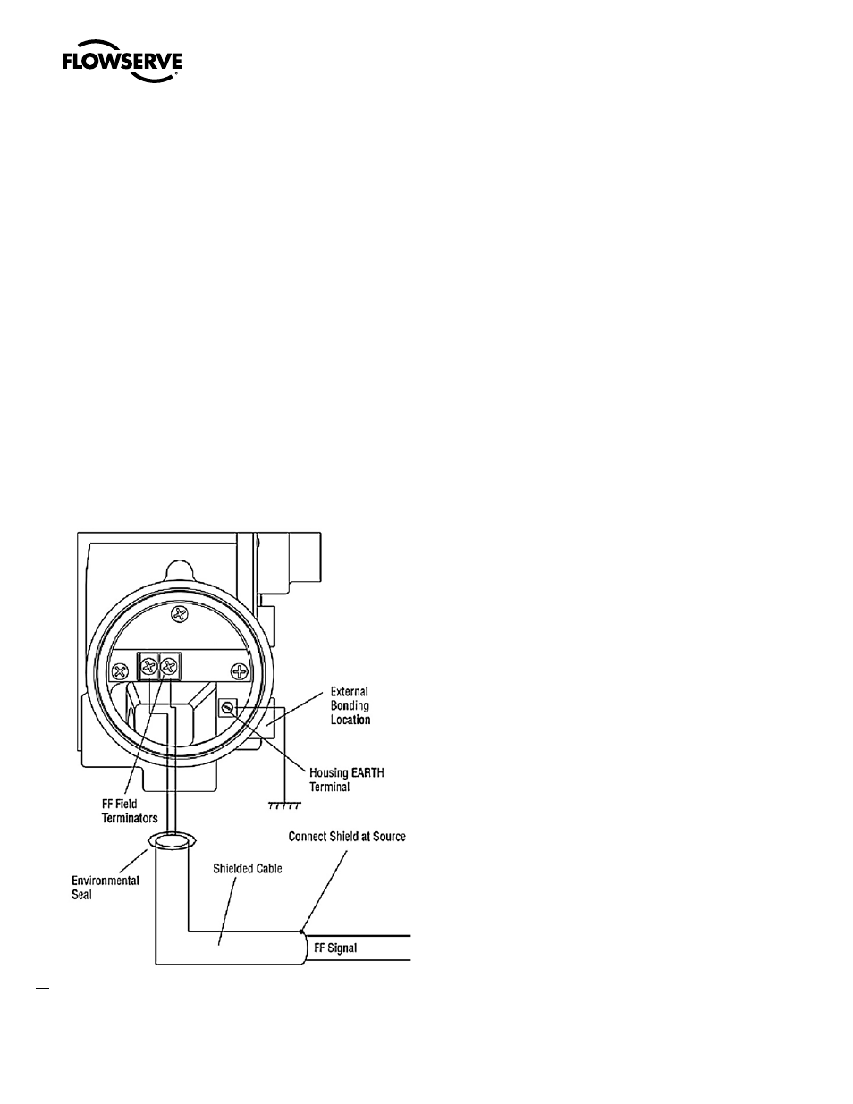
6.1 FF Command Input Wiring
The Logix 3400MD is non-polarity sensitive. Wire FF source to the
input terminals (see Figure 6). Minimum operating voltage is 9 VDC.
The FF signal to the Logix 3400MD digital positioner should be in
shielded cable. Shields must be tied to a ground at only one end of
the cable to provide a place for environmental electrical noise to be
removed from the cable. In general, shield wire should be connected
at the source. Refer to guidelines in FF AG-140 and FF AG-181 for
proper wiring methods.
6.2 Grounding Screw
The green grounding screw, located inside the termination cap,
should be used to provide the unit with an adequate and reliable earth
ground reference. This ground should be tied to the same ground as
the electrical conduit. Additionally, the electrical conduit should be
earth grounded at both ends of its run.
c
DANGER: The green grounding screw must not be used to
terminate signal shield wires.
Figure 6: Field Termination
6
Wiring and Grounding
Guidelines
(See Figure 6)
c
DANGER: This product has electrical conduit connections in either
thread sizes 1/2” NPT or M20 which appear identical but are not
interchangeable. Housings with M20 threads are stamped with
the letters M20 above the conduit opening. Forcing dissimilar
threads together will damage equipment, cause personal injury
and void hazardous location certifications. Conduit fittings must
match equipment housing threads before installation. If threads
do not match, obtain suitable adapters or contact a Flowserve
representative.
c
DANGER Any unused cable entries are to be closed off with
appropriately certified blanking devices.
c
DANGER: When using cable glands, ensure that they are
appropriately certified.