2 initial dip switch settings, 3 description of configuration dip switch settings – Flowserve 3400MD Digital Positioner User Manual
Page 16
Logix 3400MD Digital Positioner FCD LGENIM3404-08-AQ –5/15
16
7.2 Initial DIP Switch Settings
Before placing the unit in service, set the DIP switches in the Configu-
ration boxes to the desired control options. A detailed description of
each DIP switch setting follows.
NOTE: The Logix 3400MD positioner reads the DIP switch settings
each time the RE-CAL button is pressed. If a FF handheld or Host
software is used to configure and then calibrate the positioner, the
DIP switches are not read. The auto-tune adjustment switch labeled
“GAIN” is always live and can be adjusted at any time.
Transducer block settings will always override the DIP switch settings
until the RE-CAL button is pressed.
7.3 Description of Configuration DIP
Switch Settings
The first six DIP switches are for basic configuration. The function
of each switch is described below.
Air Action
This must be set to match the configuration of the valve/actuator
mechanical tubing connection and spring location since these deter-
mine the air action of the system.
ATO (air-to-open)
Selecting ATC if increasing output pressure from the positioner is
tubed so it will cause the valve to close.
ATC (air-to-close)
Selecting ATC if increasing output pressure from the positioner is
tubed so it will cause the valve to close.
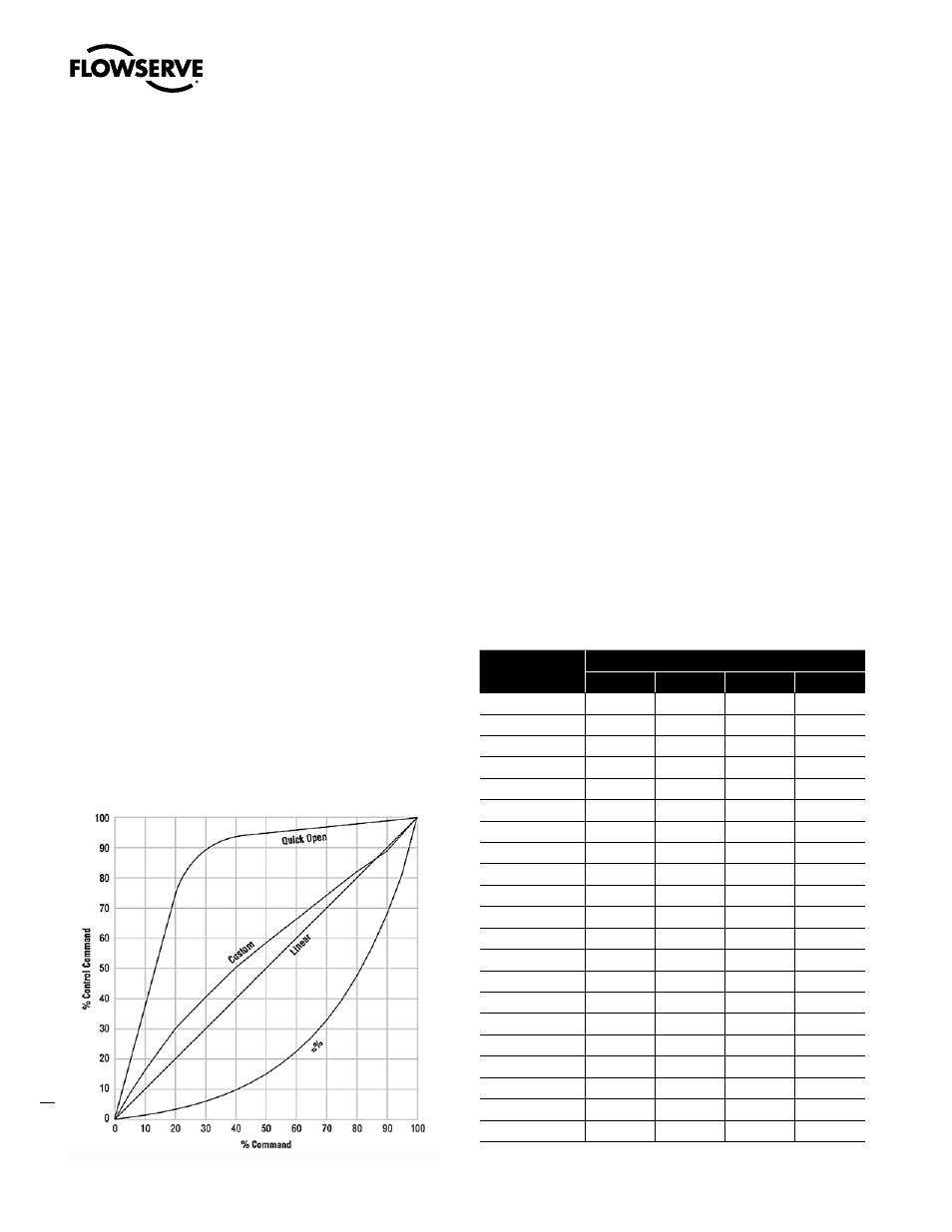
Figure 9: Default Custom Characterization
Pos. Characterization
Linear Select Linear if the actuator position should be directly
proportional to the input signal.
Other Select Other if another characteristic is desired, which is set in
conjunction with the Control_Flags parameter in the transducer block.
Optional Pos. Characterization
If the Pos. Characterization switch is set to Other then the CURVE_
SELECT parameter is active with the following options:
=% The =% option will characterize the actuator response to the
input signal based on a standard 30:1 equal percent rangeability
curve.
QO Quick open is based on a standard industry quick-open curve.
Custom If Custom is selected, the positioner will be characterized
to a custom table that must be set-up using a properly configured
475 handheld or other host software. Custom characterization can
be thought of as a “soft CAM.” The user can define a characterization
curve using 21 points. The control will linearly interpolate between
points. Points do not have to be equally spaced in order to allow more
definition at critical curve areas. The default values will linearize the
output of a valve with an inherent =% characteristic (e.g. ball valves.)
Table 8: Characteristic Curve Data
% Command
% Control Command
=%
Linear
Custom
QO
0
0
0
0
0
5
0.62
5
8.66
18.8
10
1.35
10
16.24
37.6
15
2.22
15
23.17
56.4
20
3.25
20
30.11
74.0
25
4.47
25
35.31
84.3
30
5.91
30
40.51
90.0
35
7.63
35
45.42
92.0
40
9.66
40
50.34
93.4
45
12.07
45
54.40
94.2
50
14.92
50
58.47
94.8
55
18.31
55
62.39
95.5
60
22.32
60
66.31
96.0
65
27.08
65
70.27
96.5
70
32.71
70
74.23
97.0
75
39.40
75
78.17
97.5
80
47.32
80
82.11
98.0
85
56.71
85
85.50
98.5
90
67.84
90
88.89
99.0
95
81.03
95
94.45
99.5
100
100.00
100
100.00
100.0