Diagram and details of the ILS24 electrical system
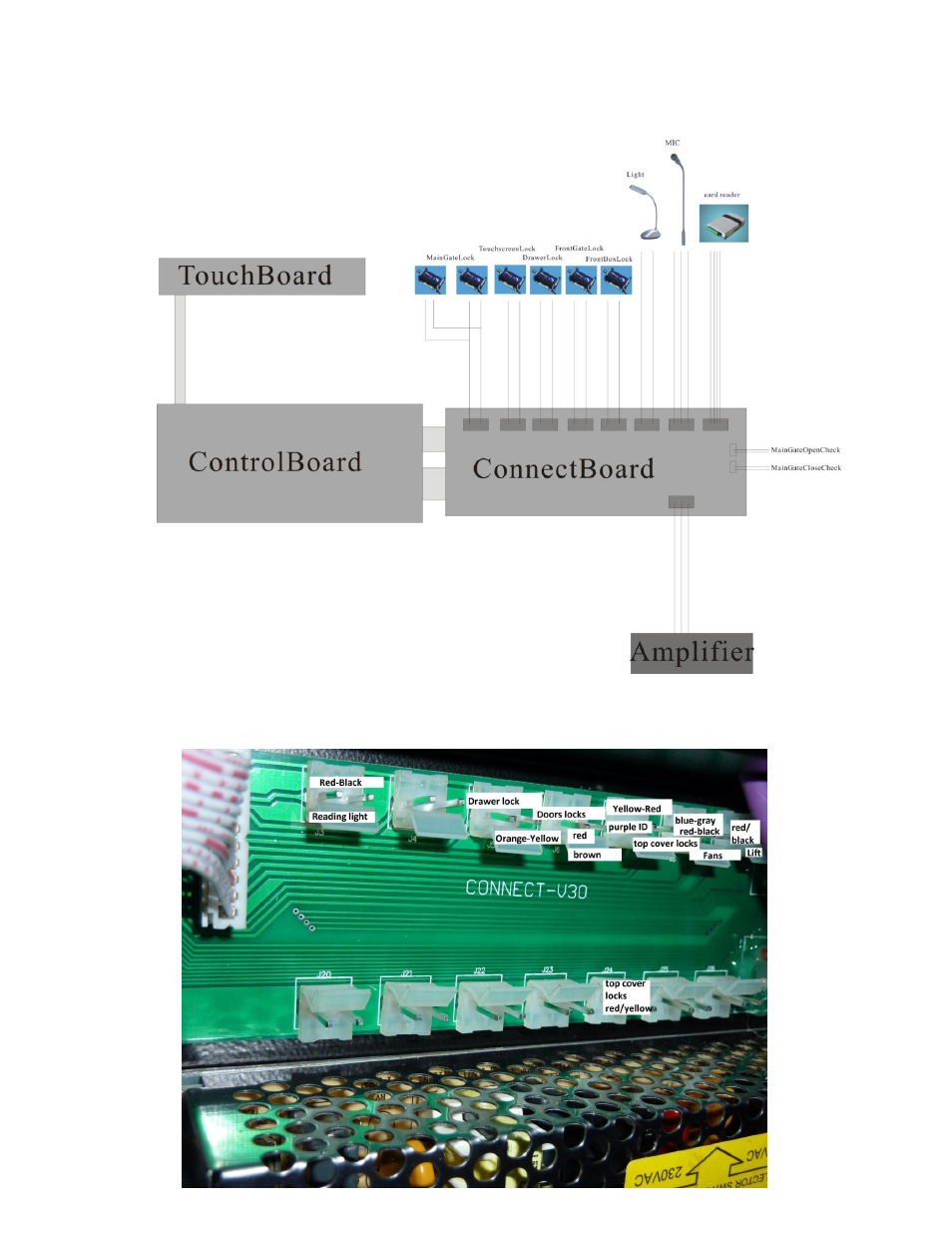
1. See below for the connection board pins (right board) In this example the 2
nd
molex pins (J4) are
not used, these are for the lock of the 12” side panel The bottom row is a mirror image of the
top row with the same functions.