ILS ILS24H Installation User Manual
Page 11
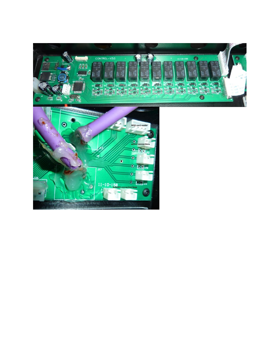
2. The left board contains microphone damping circuitry, 11 relays (hear them tick when using the
touch panel) and a programmable MCU
3. The access card reader is
programmable as well by connecting to
a serial connection of a PC.
4. The bottom connectors on the
left picture serve a particular purpose:
the left socket can either connect its
pins for on-off or for a moment switch.
This is then operated from the spare
second button from the bottom on the
6-button touch panel. The type of
function is set by a jumper on the left of
the relay board.
5. The right connector is connecting when the top cover is opened after using the RFID key. This
lead is typically intended for driving and switching on the bank of high voltage sockets on a
SURGEX or other bank switching power conditioner.
7. Your system may be equipped with various other components:
a. HP Compaq SSF PC or ILS Rack PC supporting the main monitor with sho-Q software
for interaction and projection and/or to function as control system.
b. Various control systems and switchers by AMX, Creator, Crestron, Extron.
c. Control system software by FHCS and room-Q
d. Sho-Q interactive presentation delivery, annotation overlays and whiteboard
Please consult the respective manuals of these systems.