ILS ILS24H Installation User Manual
Page 5
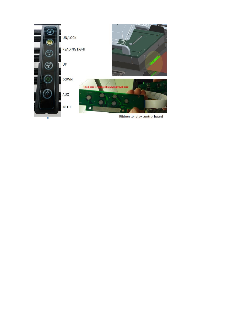
10. Press the top
button (Unlock) You will
hear a click noise and in the
next 10 seconds you can
open the drawer . You can
open the rack doors by
pushing them inward, after
which they jump open.
You can open the drawer
and shift the optional 12”
panel to the right in the
same time. After about 10
seconds the locks go into
close positions.
11. You will see 2 rack shelves installed, the upper one intended for the PC, the lower smaller one
for the Panasonic player. Below that you find rack nuts, feel free to insert those in desired
positions, the nuts are intended to support 3 Rack-unit devices, such as matrix switchers,
control systems and e.g. a power conditioner and power switch.
12. After opening the top cover, you have found a support plateau for mostly the WACOM 2200 HD
pen-interactive monitor, it has the electrical lift controlled by the up/down buttons on the 6
button touch strip and manually allows for angular adjustment of the monitor. This is very quick
process by grabbing the monitor on the audience side and pull it to the desired angle, to lower
the angle, first pull it all the way up then down, then adjust to the desired height.
13. [Configurations at PNU only]:
a. ILS24N17FLD-type (studio version): VESA mount 75x75 and 100x100 off center to the
left to install the Sympodium ID370, with flush next to it, brackets that allow fixing
inside/between these an AMX NXD435
b. ILS24N17CLA-type (lecture hall version): Center VESA mount 75x75 + 100x100 for
attaching the ID370, whilst opening the drawer, reveals a tilt and lift mechanism for
installing an AMX 1200VG by using its VESA mount 75x75 back panel.
c. ILS24N17OBX-type (classroom version): Center VESA mount 100x100 on tilt plane for a
regular 17 inch monitor such as the DELL170P or 170S.
14. The electrical lift option for the main interactive monitor, for pen-interactivity and the larger
monitors, the electrical lift is a requirement. Note: the up/down buttons will only operate if the
sensors in the top register that the top cover has been moved all the way out to the left and
the 12” touch panel side table all the way to the right. If there is a potential that the monitor
could hit either of these, the sensors will prevent the lift from operating. If the lift does not
operate first verify if the top cover and the side panel are not blocking this function.