ILS ILS24H Installation User Manual
Page 4
1. There is a lock and key on the top center, which blocks the panel from being lifted out. Make
sure it is parallel to the front panel so that it is in the unlock position.
2. This panel can be lifted upwards about 7-8 cm and then pull forward. (this may take some force.
By adjusting the corners, this can be made easier, see later in this manual)
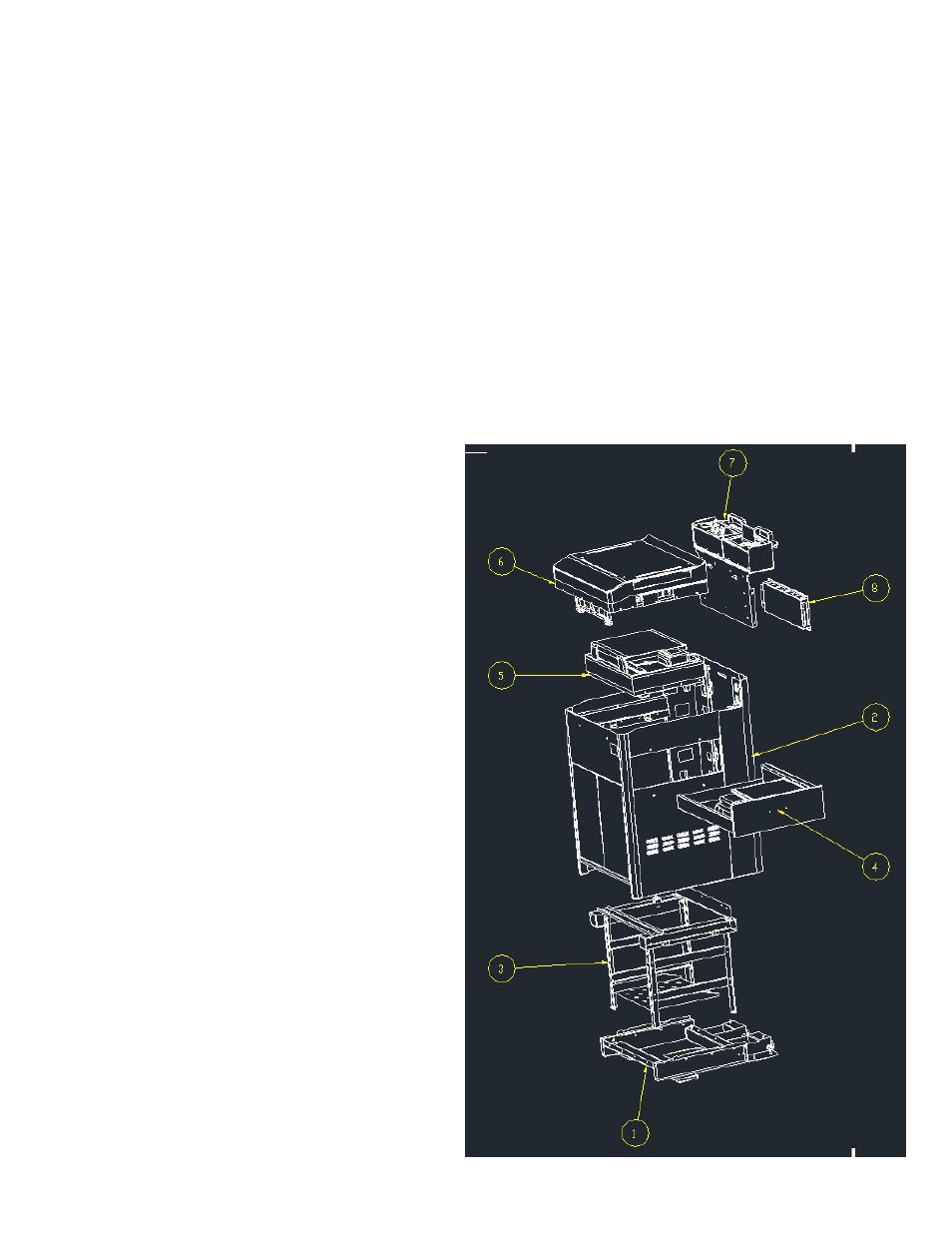
3. After opening, you can see the inside: the back of the 19”rack, a black box that houses the ILS
electronics, relays, patch board and 12V + 24V power supplies. The box has a cover for service
access. (item with arrow 8 in below drawing)
4. Notice there are 2 power extension cables, one is tucked in the top and serves as power for the
top power socket; the other is general system power. The IEC plug is intended to plug into the
permanent power outlet of e.g. a SURGEX power service system. For now, use a regular cable to
connect and power up the system.
5. The top cover can be opened now. It is able to open without power initially as ILS has taped the
locks of the top cover in the downward position, this allows opening the system without power.
After full access has been arrange and
tested with the RFID card for secure
access, the tape can be removed.
6. The top cover only opens and closes
with the RFID card; rack doors, the 12”
side panel [if present] and the drawer
are operated from the presenter side of
the lectern using the top UNLOCK
button after power has been given to
the lectern.
7. Notice that the cable guides have not
been installed, to allow access to the
back of the rack, in which you may opt
to install for example an EXTRON patch
panel first. Rack-nuts are already in
place for this in the middle of the rack.
The cable guides and screws are found
inside the large side drawer.
8. Modularity of the lectern assembly
allows us to accommodate specific
customer demands, we delivered 3
versions where the monitor base (arrow
5), the lift and the drawer (arrow 4) had
variation in components.
9. Now open the drawer and the 19” rack
access doors: After opening the top
cover and applying power, notice on the
right a strip of buttons that now have a
blue light under the buttons.