Typical faults and causes – K-Patents PR-33-S Troubleshooting Guide User Manual
Page 7
TROUBLESHOOTING GUIDE
FOR PR-33-S AND PR-33-AC
7 (10)
January 9, 2015
K-PATENTS OY
•
Postal Address: P.O.Box 77, FI-01511 Vantaa, Finland
•
Street Address: Elannontie 5, FI-01510 Vantaa, Finland
•
Tel. int.+358 207 291 570
Fax int.+358 207 291 577
•
•
www.kpatents.com
•
VAT No. FI03035575
•
Business ID 0303557-5
•
Registered in Helsinki
instructions manual.
TEMP = Temperature element of the instrument is located at the tip of the sensor probe, thus the
temperature element is one of the first components affected by instrument leakages. Typically the leakages
are detected from abnormal temperature readings as the resistance of the PT-1000 temperature element
increases when corroded. If the electric circuit is cut off, the temperature will drop to -273.14 °C.
QF = Quality of the optical image which is individual for every application. Quality factor expresses the
steepness of the slope in the optical image and thus the stability of the measurement. However, in some
applications QF values might be about 40-50 which is still good, whereas in other applications the QF is
about 170. Therefore, it is important to keep track of the QF value so that the changes in QF are taken
record of. Significantly decreased QF values are generally seen with bad optical images that is a result of
prism coating or erosion.
LED = Optimal value for LED is between 3-25 %. Higher LED values indicate blockage on the light path,
which can be a result of coating or prism erosion. High LED values are often shown with bad optical images,
i.e. with weak slopes.
HD TEMP = High temperatures can damage the electric components. Prolonged high temperatures inside
the sensor may result in short circuits on the electric boards and component failures.
HD HUM = High humidity inside the sensor is harmful to the electric components. High humidity could also
indicate leakages, but it is common that the humidity starts to increase inside the instrument after the dryer
got saturated over time. Generally, high humidity can be resolved by changing the dryer, which is also
recommended every time the sensor cover is removed.
Typical faults and causes
1. Description: Measurement is constantly showing 0 in DCS
Cause(s): Error message on the measurement status, such as No optical image, no sensor, short circuit, etc.
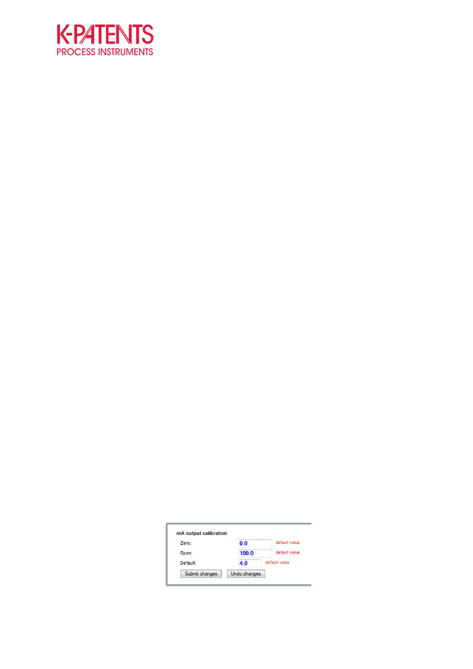
During certain error messages the instrument gives “default” mA-output, this is configured to give 4 mA as
preset.
Figure 8
Default mA-output activation when the instrument has a measurement related error message