Installation, Top vent venting runs, C-series dv – Montigo C34DV User Manual
Page 7: Installation of rear vent dv, A) through-the-wall installations
Page 7
C-Series DV Gas Fireplace
Part No. XG0170 - 080610
Installation
Top Vent Venting Runs
For the C-Series DV Top Vent, there are two types of installations:
A) Through-The-Wall Installations and B) Vertical (Through-The-Roof)
Installations.
A) Through-The-Wall Installations
Before you install any venting, you must determine whether the venting
run will be acceptable. Unacceptable venting can affect the fireplace's
combustion.
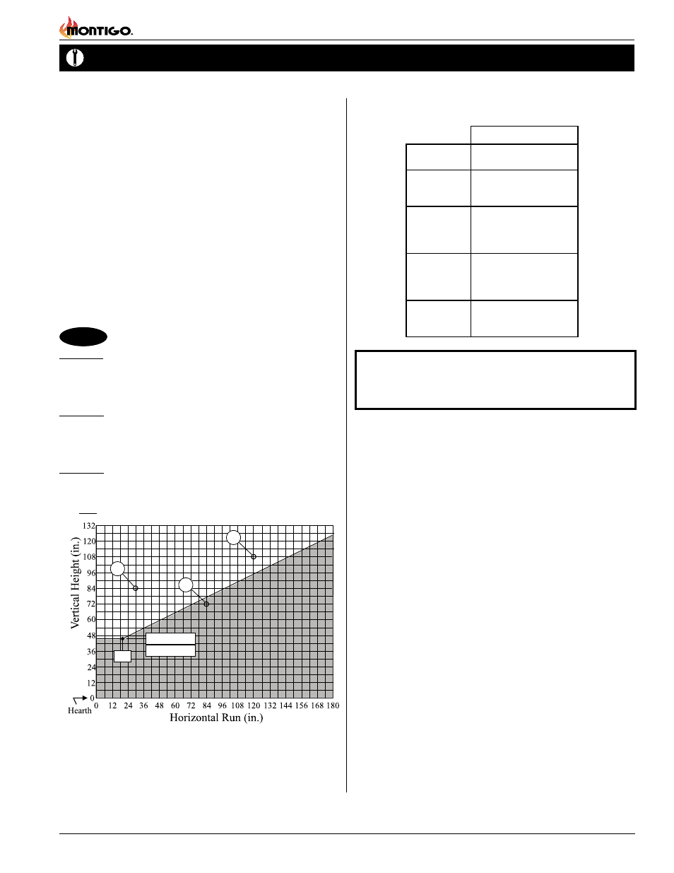
The Venting Graph
Measure the vertical height from the fireplace hearth to the centre of
the termination and the horizontal run from the from the fireplace flue
collar to the wall flange of the termination. Plot on the Venting Graph
(Fig. 9) with an 'X'.
If the 'X' falls on or above the top boundary of the shaded area, the
installation is acceptable.
C-Series DV
Example A: (Acceptable Installation)
If the vertical dimension from the hearth is 84" and the horizontal run to
the wall flange of the vent termination is 30", this would be an acceptable
installation.
Example B: (Acceptable Installation)
If the vertical dimension from the hearth is 108" and the horizontal run to
the wall flange of the vent termination is 120", this would be an accept-
able installation.
Example C: (Unacceptable Installation)
If the vertical dimension from the floor of the fireplace is 72" and the
horizontal run to the wall flange of the vent termination is 84", this would
NOT be an acceptable installation.
Figure 9. C34-DV, C38-DV Top Vent Venting Graph
5" / 8" Venting
A - Termination
PTO-3 (3" Length)
PTO-3F (3" Length)
B - Stucco Kits
MSR (Stucco Frame)
MOSR (Stucco Can)
BSR ( Brick Can)
C - Flex Sections PFL-1 (12" Section)
PFL-2 (24" Section)
PFL-3 (36" Section)
PFL-4 (48" Section)
D - Rigid
Sections
PEXT-1 (12" m/f Section)
PEXT-2 (24" m/f Section)
PEXT-3 (36" m/f Section)
PEXT-4 (48" m/f Section)
E - Elbows
PEL-90MM (m/m 90° Elbow)
PEL-90FF (f/f 90° Elbow)
PEL-90FM (f/m 90° Elbow)
NOTES: All dimension lengths for vertical or horizontal runs are
measured from centre of the vent pipe. Venting runs must
fall within the limits set by the venting graph (see Figure 9).
C-Series DV
B
A
18”
C
C38 42 7/8”
C34 39 7/8”
Installation of Rear Vent DV
The following venting components are available for the Rear Vent
installation: