Maintenance, General, Cleaning – Montigo M38DV PFC User Manual
Page 13: Pilot burner adjustment, Gas control valve, Caution, Page 13, M38dv-pfc peninsula gas fireplace
Page 13
P/N XG0202
M38DV-PFC Peninsula Gas Fireplace
Maintenance
General
Have the fireplace installation inspected yearly, including a visual
check of the vent system, the burner and the pilot flame. For con-
venience a 1/8" manifold pressure tap is supplied on the gas valve
for a test gauge connection. See Figure 19.
For Natural Gas this appliance requires a minimum inlet pressure
of 5.5" W.C. and a manifold pressure of 3.5" W.C.
For Propane Gas this appliance requires a minimum inlet pres-
sure of 11" W.C. and a manifold pressure of 10" W.C.
Always keep the fireplace area clear and free of combustible
materials, as well as gasoline and other flammable vapours and
liquids.
Do not use this appliance if any part has been under water. Imme-
diately call a qualified service technician to inspect the appliance
and to replace any part of the control system and any gas control
which has been under water.
CAUTION
•
Fireplace gas control must be in the “OFF” position and pilot
and main burners extinguished when cleaning appliance with
a vacuum.
• Glass and logs can get very hot. Handle only when cool.
Cleaning
When the fireplace is first activated, there may be some smoking and
a visible film may be left on the glass. This is a normal condition, and
is the result of burning the protective coatings on new metal.
Glass must be cleaned periodically to remove any film (a normal
bi-product of combustion) which may be visible. Film can easily
be removed by removing the door, as shown on page 10. Handle
the door carefully, and clean it with glass cleaners. One of the
most effective products is Kel Kem.
Silicone seals on inner door during initial firing will "off gas",
leaving a visual deposit of a white substance on combustion
chamber walls. This can easily be removed by following the steps
described above.
Use a vacuum cleaner or whisk broom to keep the control com-
partment, burner, and firebox free from dust and lint.
Logs may be cleaned periodically with a vacuum to remove soot.
WARNING:
Do not attempt to clean glass when hot.
Do not clean glass with abrasive materials as any glass etch-
ing may cause premature glass failure.
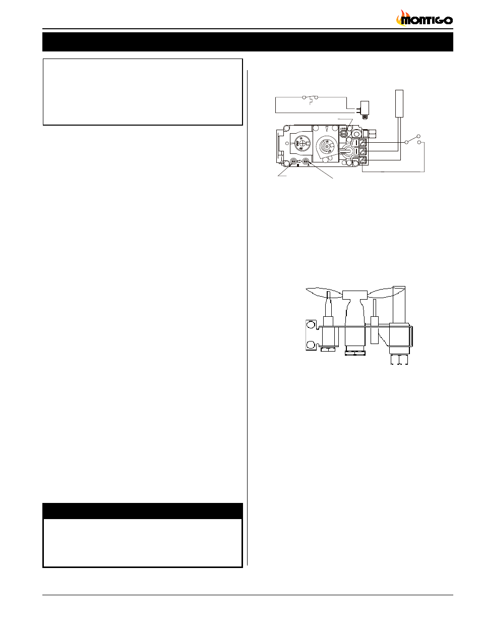
Pilot Burner Adjustment
1. Locate Pilot Adjustment Screw.
(See figure 19.)
2. Adjust pilot key to provide properly sized flame.
(See figure 20).
3. After installing or servicing, leak test with a soap solution with
main burner on. Coat pipe and tubing joints, gasket etc. with soap
solution. Bubbles indicate leaks. Tighten any areas where the
bubbles appear until the bubbling stops completely.
Figure 20.
Pilot Burner
Gas Control Valve
Figure 19.
Sit Nova 820 gas valve.
Manifold Pressure
Test Connection
Pilot Adjustment Screw
Vent Safety Switch
Inlet
Pressure
Power
Generator
Thermocouple
Connection
Wall Switch
T
P
-T
H
T
P
T
H
Secondary Limit