Installation, Caution, Tuscany – Montigo 34DVI Tuscany User Manual
Page 10: Installing the accessories, Installing the log set: model# 34hdvi, Page 10, Gas fireplace insert, Figure 27f. front left log, (log f), Figure 27c. top left log, (log d), Air inlets
Page 10
Tuscany
Gas Fireplace Insert
P/N XG0515
Installation
Irritant
Cutting
Watch your step
Slippery floor
High temperatures
Glass hazard
Danger of suffocation
High voltage
Toxic
Flammable materials
Corrosive
Fork lift trucks
Danger overhead crane
Explosion risk
Oxidising
Danger of death
Biohazard
Laser Radiation
Danger of entrapment
Hot surface
General Warning
Blank
Gas bottles
Watch for
falling objects
Electricity
Danger for cutter
Entrapment hazard
Battery hazard
Rotating parts
Low temperature
Strong magnetic field
Optical radiation
Non ionizing
radiation
Radiation
Hazardous to the
Environment
Danger of harming
your hands
cAUTIOn
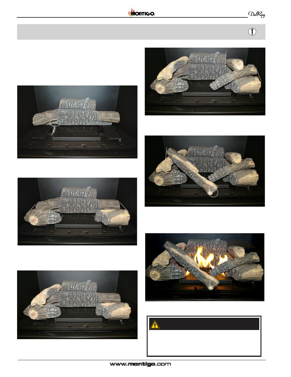
If logs are not placed properly, excessive sooting
will result.
The surface of the logs will crack due to the heat
from the flames. This is a normal occurrence.
Installing the Accessories
Figure 27f. Front Left Log, (Log F).
Installing the log set: Model# 34HDvI
The tuscany 34HDvI* is supplied with a six ceramic fibre log logset.
Unpack the logs and handle them very carefully.
step 1. Remove the glass door as described in the previous Instructions.
Air Inlets
Pilot Assembly
Fireplace Base
Rear / Bottom Log
Notch in Log
Log A
Air Inlets
Fireplace Base
Log D
Figure 27c. Top Left Log, (Log D).
Air Inlets
Fireplace Base
Log E
step 5. Place Front Left log (Log D) as shown in figure 27c.
Figure 27e. Top Right Log, (Log E)..
step 6. Place Front Right log (Log e) as shown in figure 27e.
Fireplace Base
Log F
Air Inlets
Fireplace Base
Log C
Log B
step 7. Place Front Left log (Log F) as shown in figure 27f. Set notch
in lower end of Log F against stile on Log Grate.
Figure 27g. Completed Logset.
Figure 27a. Bottom Rear Log, (Log A).
step 2. Place the bottom Rear log (Log A) as shown in figure27a.
Figure 27b. Left front Log, (Log C) and Right front Log, (Log B).
step 3. Place the bottom Right log (Log B) and bottom Left Log, (Log
C) as shown in figure 27b.