Installation, Tuscany – Montigo 34DVI Tuscany User Manual
Page 8
Page 8
Tuscany
Gas Fireplace Insert
P/N XG0515
Installation
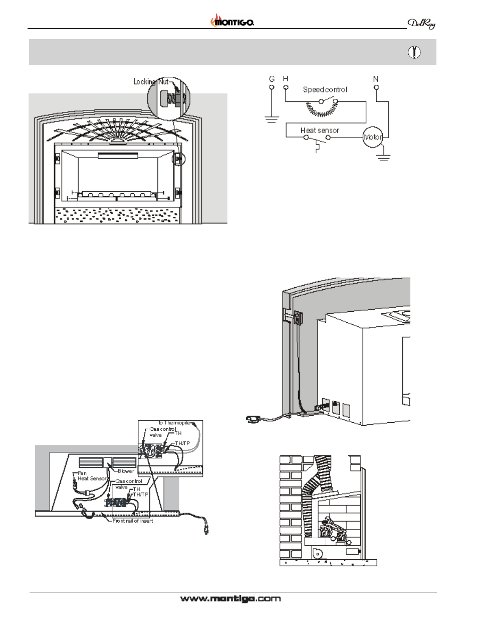
Figure 11c. Installing the fan switch assembly.
Wiring
To be completed before positioning the Insert in the fireplace.
Installations in canada must be electrically grounded in accordance
with csA c22.1 Canadian electrical Code Part 1 and/or Local Codes.
Installations in the usA must be grounded in accordance with local
codes or, in the absence of local codes, with the National electrical
Code, AnsI/nFPA 70-1987.
Figure 10c. Attaching the faceplate and tightening the
locking nuts.
Figure 11a. Connecting the wires to complete the fan
speed control and ON-OFF switch circuits.
Figure 12. Slide the insert into place.
Wiring Instructions for the Fan switch circuit
6. Connect the wire with the plastic (Molex) connector on the left side of
the control compartment to the wire which leads to the Fan Sensor
Switch.
Run the fan's power cord out through the small notch on the bottom
left side of the faceplate.
Figure 11b. Wiring Schematic for the fan circuit.
Wiring Instructions for the on/off circuit
7. Connect the wires on the right side of the insert's control compartment
to the TH and TP-TH terminals on the gas control valve. The wires
can be connected to either terminal, as there is no polarity on this
circuit.
9. Install the fan speed control and toggle switch assembly. Slide the
assembly into the location on the top right of the faceplate as shown
from a reverse angle in figure 11b.
10. Centre and slide the Tuscany in it's location.