ONICON F-5200 Inline User Manual
Page 11
11451 Belcher Road South, Largo, FL 33773 • USA • Tel +1 (727) 447-6140 • Fax (727) 442-5699 • [email protected]
F-5200 Inline Thermal Mass Flow Meter Manual 05/14 - 0763-4 / 19476
Page
11
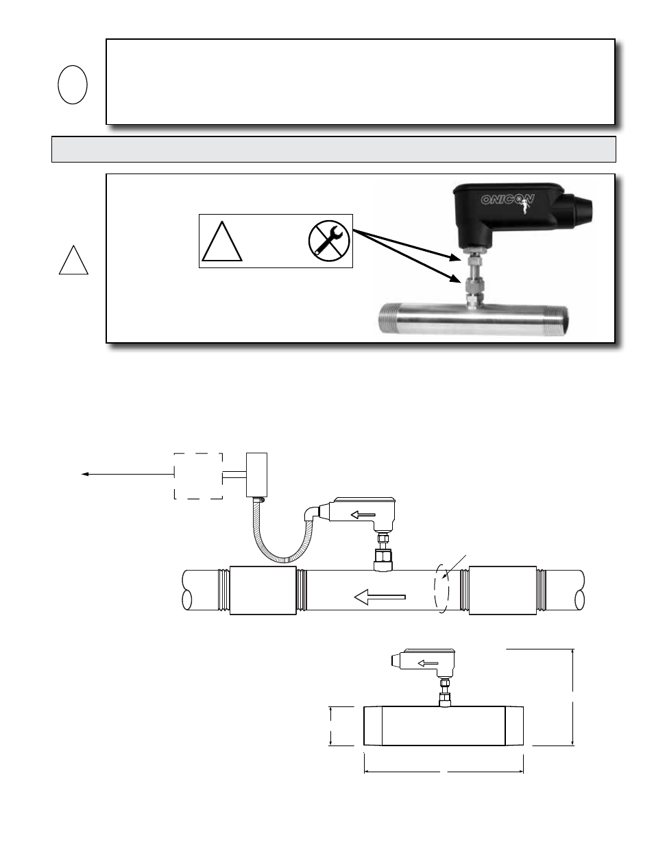
ONICON Inline Thermal Mass Flow Meters are provided with either threaded of flanged process
connections. Threaded meters are provided with male NPT threads and flanged meters are
provided with ANSI class 150 or class 300 flanges. Flow meters should be installed in accordance
with the requirements of section 3.1 INSTALLATION SITE SELECTION.
ONICON does not supply gaskets for flanged meters.
3.2.1 Threaded Meter
FLOW DIRECTION
D
L
H
D
L
H
FLOW DIRECTION
Built-in flow conditioner
Output signal(s)
to control system
Optional
ONICON
Display
FLOW
FLOW DIRECTION
IMPORTANT NOTICE
Always use the maximum available straight run. When more than the minimum required straight
run is available place the meter such that the excess straight run is upstream of the meter location.
The flow meter must also be properly installed with respect to the direction of flow. Installing the
meter with the flow arrow pointing in the wrong direction will result in significant errors in the
flow measurement.
i
3.2 MECHANICAL INSTALLATION
!
DO NOT LOOSEN
THESE FITTINGS
WARRANTY VOID
IF REMOVED
!
1500 North Belcher Road, Clearwater, FL 33765 • Tel (727) 447-6140 • Fax (727) 442-5699
www.onicon.com • [email protected]
F-5200 Inline
Thermal Mass Flow Meter
Installation and Operation Guide
11-11
0763
WARNING