ONICON F-5200 Inline User Manual
Page 9
11451 Belcher Road South, Largo, FL 33773 • USA • Tel +1 (727) 447-6140 • Fax (727) 442-5699 • [email protected]
F-5200 Inline Thermal Mass Flow Meter Manual 05/14 - 0763-4 / 19476
Page
9
SECTION 3.0: INSTALLATION
WARNING
This flow meter may be installed in pipes which are under high pressure or pipes filled with
combustible gases. Accidents with these systems can cause serious injury or death. Only persons
experienced with high pressure and/or combustible gas distribution systems and fluid metering
should attempt to install, adjust, or remove the flow meter. Please read all instructions carefully
before attempting to install or service a flow meter.
!
ONICON will be happy to assist with technical recommendations and to provide guidance by phone
or e-mail. On-site field engineering, installation and service are also available at an additional cost.
3.1 INSTALLATION SITE SELECTION
Install the flow meter where it will be accessible for personnel to perform necessary periodic
maintenance. The clearance required for installation is a minimum of 9” from the pipe wall
to the nearest obstruction above the electronics enclosure. Refer to Section 1.5 WORKING
ENVIRONMENT for additional considerations.
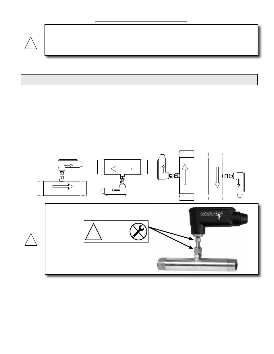
ONICON insertion style flow meters must also be correctly oriented in the pipe with respect to
the direction of flow.
The drawings below illustrate the relationship between flow direction and the orientation of the
meter when installed in the pipe. Contact ONICON for assistance if this relationship does not
allow for proper installation.
Flow
Flow
Flow
FLOW DIRECTION
FLOW DIRECTION
FLOW DIRECTION
Flow
FLOW DIRECTION
!
DO NOT LOOSEN
THESE FITTINGS
WARRANTY VOID
IF REMOVED
!
1500 North Belcher Road, Clearwater, FL 33765 • Tel (727) 447-6140 • Fax (727) 442-5699
www.onicon.com • [email protected]
F-5200 Inline
Thermal Mass Flow Meter
Installation and Operation Guide
05-12
0763-1 / 19476
WARNING
GENERAL PRACTICES:
1.
For best results, install the flow meter in a straight run of pipe, free of bends, tees,
valves, transitions and obstructions.
2.
Straight run requirements vary based on the nature of the upstream obstruction.
See the table on page 10 for guidelines in determining upstream straight run
requirements. Depending upon specific location details, more or less straight run
may be required to produce a satisfactory flow profile.