ONICON F-5200 Inline User Manual
Page 16
11451 Belcher Road South, Largo, FL 33773 • USA • Tel +1 (727) 447-6140 • Fax (727) 442-5699 • [email protected]
F-5200 Inline Thermal Mass Flow Meter Manual 05/14 - 0763-4 / 19476
Page
16
SECTION 4.0: START-UP & COMMISSIONING FOR ONICON
INLINE THERMAL MASS FLOW METERS
4.1 HELPFUL HINTS FOR START-UP & COMMISSIONING
A step-by-step procedure and companion worksheet are located on the next two pages. Please
read all installation instructions carefully before proceeding with start-up and commissioning.
Please read these helpful hints before proceeding with the start-up and commissioning procedure
on the next page.
1.
When measuring analog output signals, remember that current (mA) must be measured
in series, while voltage is measured in parallel. If the 4-20 mA signal is already connected
to a control system, you must break the connection and measure the signal in series.
2.
Do not attempt to rotate the electronics enclosure on the stem.
3.
Do not connect power to the analog output without first confirming that it is configured for
loop powered operation. See section 3.3.2.
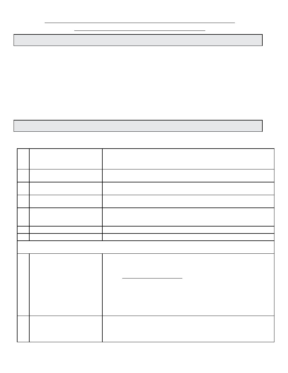
4.2 START-UP & COMMISSIONING
Please read the entire procedure before proceeding. A worksheet for checking off the following
steps and recording measured values is located on the next page.
1. Confirm flow meter location.
Confirm adequate straight pipe
run to achieve desired results.
Is the meter located in the correct location as required by the plans?
Compare actual straight pipe upstream and downstream of the meter location to
recommended distances identified in this manual.
2. Confirm orientation.
Refer to the information in section 3.1 of this manual to ensure
that the meter is properly oriented with respect to the direction of flow.
3. Confirm control system
programming.
Confirm that the control system input point is properly configured for the analog
range and/or scale factor identified on the calibration tag & certificate.
4. Confirm connection to
correct ONICON display
Confirm that the flow meter serial number matches the ONICON
display (when ordered together).
5. Verify wiring before connecting
power.
Prior to connecting the power, verify that the wiring is correct as shown in this
manual and/or on additional wiring diagrams provided with the ONICON display.
If in doubt, contact ONICON for assistance before proceeding further.
6. Confirm correct supply voltage.
Verify that the supply voltage matches the voltage listed on the meter tag.
7. Connect power.
Wait approximately 45 seconds after power-on before proceeding further.
The following steps require flow in the pipe. Flow signal readings should be taken while holding the flow rate constant, if
possible. Otherwise, take the various output readings as quickly as possible.
8. Measure and record analog and
pulse outputs.
Current Output:
Scaled Output:
Refer to flow meter wiring diagram to locate the correct output
terminals. Use the following formula to calculate the flow rate from
the analog signal measurement:
SCFH = (measured current in mA - 4)
X Full Scale Flow Rate
16
Each 24VDC pulse = unit volume identified as “Scale Factor” (measure and
record time interval between pulses in seconds)
(Pulse interval (in seconds) / 3600) x Pulse weight = Pulse rate
Example: Interval between pulses is 10 seconds and each pulse is equal to 10
SCF. (10/3600) x 10 = 3600 SCFH
9.
Compare output signals to
each other and to the flow rate
displayed by the control system.
Compare the flow rate calculated in step 8 to the flow rate indicated by the
control system. Confirm that the control system is registering scaled output
pulses as they occur.
Refer to troubleshooting guide when readings are inconsistent.