ONICON F-5200 Insertion User Manual
Page 16
11451 Belcher Road South, Largo, FL 33773 • USA • Tel +1 (727) 447-6140 • Fax (727) 442-5699 • [email protected]
F-5200 Insertion Thermal Mass Flow Meter Manual 05/14 - 0756-8 / 19475
Page 16
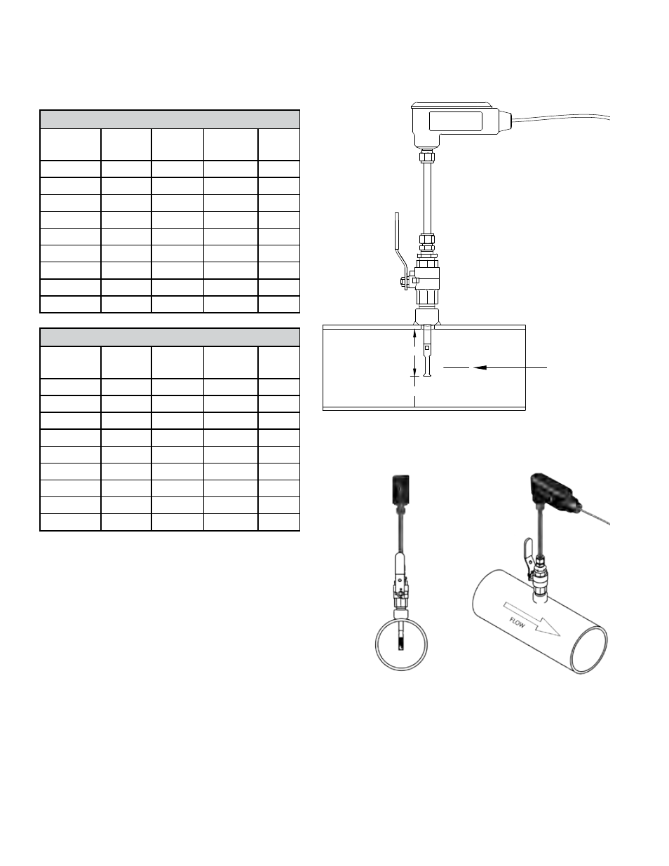
Determining the Insertion Depth
The dimension used to set the insertion depth is the “X” dimension. This dimension is
printed on the laminated tag attached to the meter and can be found in the tables below.
Schedule 40 Pipe
Nominal
Diameter
O.D.
I.D.
X
Y
1”
1.315
1.049
Bottom
N/A
1.25”
1.660
1.380
Bottom
N/A
1.5”
1.900
1.610
0.20”
1.56”
2”
2.375
2.067
0.40”
1.82”
2.5”
2.875
2.469
0.60”
2.07”
3”
3.500
3.068
0.90”
2.38”
4”
4.500
4.026
1.40”
2.86”
6”
6.625
6.065
2.40”
3.95”
8”
8.625
7.981
3.40”
4.90”
Schedule 80 Pipe
Nominal
Diameter
O.D.
I.D.
X
Y
1”
1.315
0.957
Bottom
N/A
1.25”
1.660
1.278
Bottom
N/A
1.5”
1.900
1.500
0.15”
1.56”
2”
2.375
1.939
0.35”
1.82”
2.5”
2.875
2.323
0.55”
2.07”
3”
3.500
2.900
0.80”
2.38”
4”
4.500
3.826
1.30”
2.86”
6”
6.625
5.761
2.25”
3.95”
8”
8.625
7.625
3.25”
4.90”
Inserting the Meter
1.
Insert the flow meter stem into the
compression fitting.
2.
Open the ball valve and carefully
insert the flow meter until the end
of the stem just contacts the opposite
wall of the pipe.
3.
Mark the position of the stem where it
exits the top of the compression fitting.
4.
Withdraw the stem “X” distance as
measured from the top of the compression
fitting. At the same time position the
electronics enclosure parallel to the pipe in the correct orientation relative to the
flow direction as shown. This will position the sensor with its axis in line
with the flow and in the correct direction.
Center Line
of Pipe
X
Y
ONICON