ONICON F-5200 Insertion User Manual
Page 5
11451 Belcher Road South, Largo, FL 33773 • USA • Tel +1 (727) 447-6140 • Fax (727) 442-5699 • [email protected]
F-5200 Insertion Thermal Mass Flow Meter Manual 05/14 - 0756-8 / 19475
Page 5
SECTION 1.0: INTRODUCTION
We, at ONICON Incorporated, would like to thank you for purchasing our quality American made
F-5200 Series Thermal Mass Flow Meter. As our valued customer, our commitment to you is to
provide fast reliable service, while continuing to offer you quality products to meet your growing
flow measurement needs.
1.1 PURPOSE OF THIS GUIDE
We have written this guide to provide the persons responsible for the installation, operation and
maintenance of your flow meter with the product specific information they will need. This is
NOT an electrical or plumbing trade manual.
WARNING
Please do not permit persons to install, operate or maintain this equipment unless they have a
complete knowledge of their trade skills and are competent to work on combustible gas and/or
high pressure compressed air systems, according to their individual trades. Death or permanent
injury may result from accidents with these systems.
!
This guide is the basic reference tool for all ONICON F-5200 Insertion Thermal Mass Flow
Meters. If you have not purchased all of the options, there will be references in this manual
which are not applicable to your meter(s).
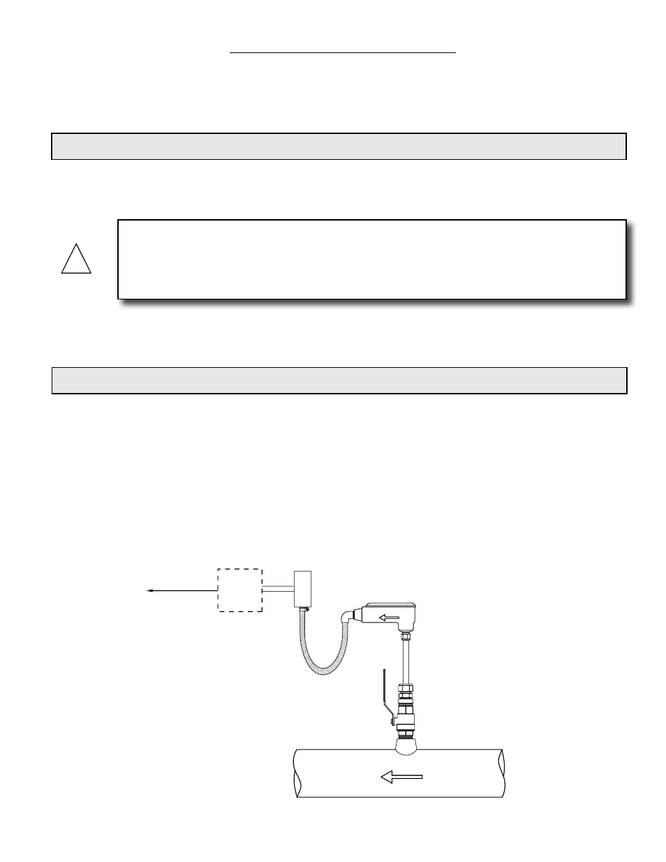
1.2 TYPICAL INSERTION THERMAL MASS FLOW METER
Each ONICON thermal mass meter has a single pair of encapsulated platinum sensors that are
in direct contact with the gas. The sensors consist of highly stable reference-grade platinum
windings. One sensor is self-heated and serves as the flow sensor. The other acts as a reference
sensor, and measures the gas temperature. Our proprietary sensor circuitry maintains a constant
temperature differential between the flow sensor and the reference sensor.
As gas flows by the heated sensor (flow sensor), the molecules of flowing gas carry heat away
and the sensor cools. The sensor circuitry continuously compensates for this cooling effect and
maintains a constant temperature differential between the two sensors. The energy required to
maintain this temperature differential is directly proportional to the mass flow. There is no need
for additional temperature or pressure compensation.
FLOW
Output signal(s)
to control system
ONICON
Display or
BTU Meter
(Optional)
FLOW DIRECTION