Connection and wiring information, Technical guide bacnet, Link interface 4 – Orion System BACnet Link User Manual
Page 4: Figure 2: bacnet, Link interface wiring figure 3: bacnet, Link interface address switch setting, Mode selection enter clear esc prev next down up, Minus, Status setpoints schedules configuration alarms, Overrides balance - test
Technical Guide
BACnet
®
Link Interface
4
Connection and Wiring Information
Modular Service Tool
Mode
Selection
ENTER
CLEAR
ESC
PREV
NEXT
DOWN
UP
6
5
4
DEC
7
0
8
1
3
2
9
MINUS
-
STATUS
SETPOINTS
SCHEDULES
CONFIGURATION
ALARMS
ON
OVERRIDES
BALANCE - TEST
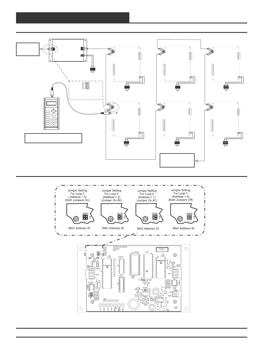
To Next VAV/CAV or MUA II
Controller On Loop
Up To 16 Controllers
Can Be Interconnected
All Programming Of Unit Controllers
Must Be Done With The Modular Service Tool
Line Voltage
BACnet Link Interface
BACnet MS/TP
LAN Connection
To BACnet
Network
24 VAC
(10 VA)
Line Voltage
VAV/CAV or MUA II Unit Controller
24 VAC
(8 VA)
Line Voltage
VAV/CAV or MUA II Unit Controller
24 VAC
(8 VA)
Line Voltage
VAV/CAV or MUA II Unit Controller
24 VAC
(8 VA)
Line Voltage
VAV/CAV or MUA II Unit Controller
24 VAC
(8 VA)
Line Voltage
VAV/CAV or MUA II Unit Controller
24 VAC
(8 VA)
Line Voltage
VAV/CAV or MUA II Unit Controller
24 VAC
(8 VA)
SHLD
T
R
Typical Terminal Blocks. All
Wiring To Be T To T, SHLD
(G) To SHLD (G) & R To R
Figure 2: BACnet
®
Link Interface Wiring
Figure 3: BACnet
®
Link Interface Address Switch Setting