Troubleshooting information – Orion System BACnet Link User Manual
Page 5
BACnet® Link Interface
Technical Guide
5
General Information
The BACnet® Link is designed to only work with the following Orion
controllers.
VAV/CAV Controller (SS1003, SS1012, Y200235, Y200301)
MUA II Controller (SS1004, Y200231, Y200306, Y200405)
CW/HW Controller (Y200311)
To determine what controller you have you must look at the label lo-
cated on the controller E-prom. If the controller label does not match
any of the SS or Y numbers listed above, your controller will not work
with the BACnet® Link.
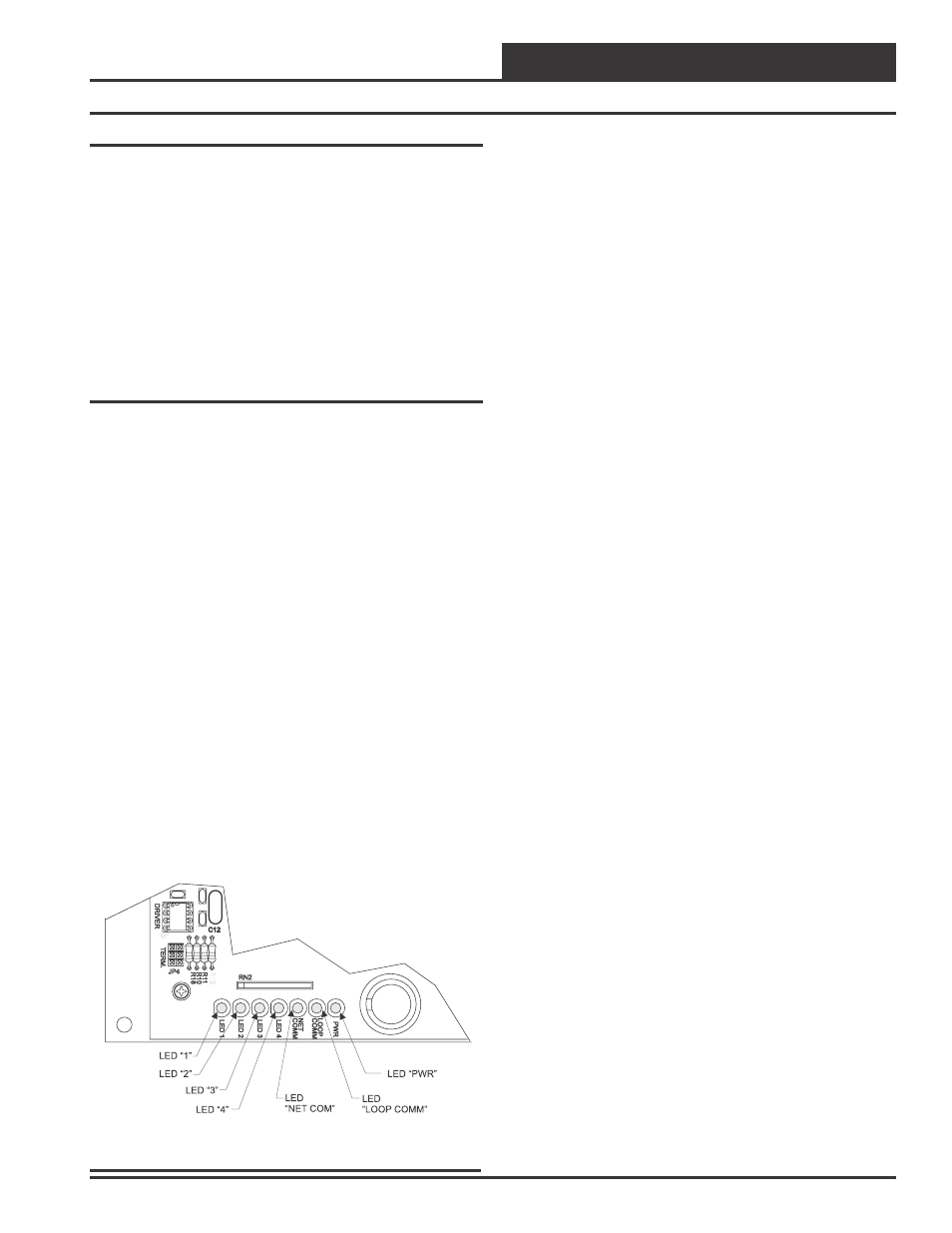
Using LED’s To Verify Operation
The BACnet® Link is equipped with LED’s that can be used for trouble-
shooting. There are seven LED’s on the BACnet® Link. Five of these
LED’s are used in troubleshooting. The LED’s and their uses are as
follows:
PWR
This LED will light up to indicate that 24 VAC power has been ap-
plied to the controller.
LOOP COMM
This LED will light up to indicate communication with the controllers
on the loop.
NET COMM
This LED will light up to indicate communication with the BACnet®
router.
LED 4
This LED is not currently used.
LED 3
This LED is also used to indicate communication with the BACnet®
router.
LED 2
This LED is used to indicate the number of controllers the BACnet®
Link is communicating with.
LED 1
This LED is not currently used.
PWR LED Operations
When the BACnet® Link is powered up, the “PWR” LED should light
up and stay on continuously. If it does not light up, check to be sure
that you have 24 VAC connected to the board, that the wiring connec-
tions are tight and that they are wired for correct polarity. The 24
VAC power must be connected so that all ground wires remain com-
mon. If after making all these checks the PWR LED does not light up,
please contact WattMaster technical support for assistance.
LOOP COMM LED Operations
When power is applied to the BACnet® Link the “LOOP COMM”
LED will also light up. The LED should flicker rapidly indicating
that the BACnet® Link is trying to communicate with the controllers
on the loop. A “flicker” is defined as a brief moment when the LED
turns off then back on. If the LOOP COMM LED does not operate as
indicated above, first power down the unit and then reapply power. If
this does not work, then contact WattMaster technical support for as-
sistance.
LED 2 Operations
When power is first applied, “LED 2” will be off temporarily then will
blink one time for each controller it is communicating with. For ex-
ample, if you have 10 controllers on the loop connected to the BAC-
net® Link then LED 2 will blink 10 times. If the amount of blinks
does not match the number of controllers connected to the loop, it
indicates there is a communications problem. The best way to find
out which board is not communicating is to go to each controller and
look at its COMM LED. The LED should be solid and will flicker
occasionally indicating communication with the BACnet® Link. If
the COMM LED does not flicker, there is no communication with that
controller.
NET COMM LED Operations
The “NET COMM” LED works the same way as the LOOP COMM
LED but it indicates that the BACnet® Link is trying to communicate
with the BACnet® router.
LED 3 Operations
When power is first applied , “LED 3” will be off temporarily and
then will blink slowly indicating communication with the BACnet®
router. If LED 3 does not blink, this means it is not communicating
with the BACnet® router. The first thing to check is the wiring be-
tween the BACnet® Link and the BACnet® router. Make sure that T
is wired to the (-) terminal of the router and R is wired to the (+)
terminal of the router.
If all of these tests are made and the controller still doesn’t operate,
please contact WattMaster Controls Technical Support at our Toll Free
number, 866-918-1100 for assistance.
Troubleshooting Information
Figure 4 BACnet
®
Link LED Locations