Warning, Caution – Partner B305 CBS Rev.7 User Manual
Page 5
-- 5 --
Fig. 2A
Fig. 2B
Fig. 2C
D
A
E
E
D
B
C
C
B
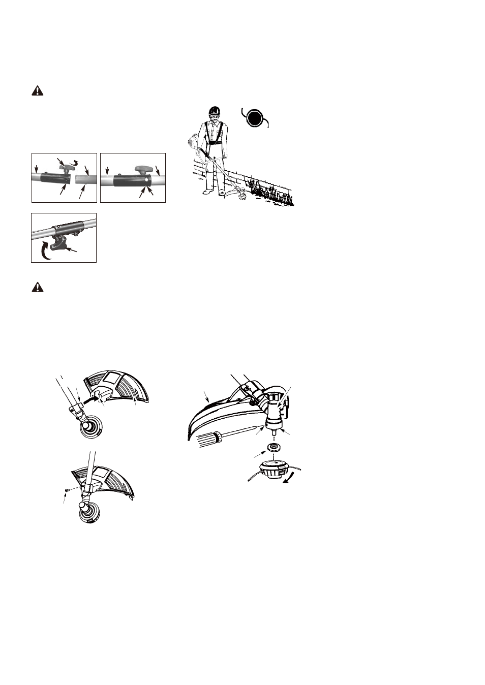
ATTACHING THE SHIELD
WARNING:
The shield must be
properly installed. The shield provides
partial protection to the operator and thers
from the risk of thrown objects, and is
equipped with a line limiter blade which cuts
excess line to the proper length.
The line limiter blade (on underside of
shield) is sharp and can cut you.
1. Insert bracket into slot on shield.
2. Pivot shield to align holes in shield and
bracket.
3. Secure shield to bracket with bolt.
Slot
Shield
Bracket
Bolt
CONFIGURING YOUR UNIT
You can configure your unit using a cutting
head for grass and light weeds, or a weed
blade for cutting grass, weeds, and brush up
to 1 cm in diameter. To assemble your unit,
go to the section for the desired
configuration and follow the instructions.
ASSEMBLY INFORMATION -
TRIMMER HEAD
TRIMMER
HEAD
NOTE: Remove the blade before attaching
the trimmer head. To remove blade, align
hole in the dust cup with the hole in the side
of the gearbox by rotating the blade. Insert a
small screwdriver into aligned holes. This
will keep the shaft from turning while
loosening the blade nut. Remove blade nut
by turning clockwise. Remove the
screwdriver. Remove both washers and
blade. See INSTALLATION OF THE
METAL BLADE for illustrations. Be sure to
store all parts and instructions for future
use. Never use the trimmer head with the
metal blade installed.
INSTALLATION OF THE TRIMMER
HEAD
NOTE: If your unit has a plastic cover over
the threads on the threaded shaft, remove
the covering to expose the threads. Before
installing the trimmer head, make sure the
dust cup and retaining washer are
positioned on the gearbox.
Retaining washer
Dust cup
Gearbox
Aligned holes
Shield
NOTE: Make sure all parts are properly
installed as shown in the illustration before
installing the trimmer head.
1. Align hole in the dust cup with the hole in
the side of the gearbox by rotating the
dust cup.
CAUTION:
The release button must
be in the primary hole and the knob securely
tightened before operating this unit.
2. While firmly holding the attachment (B),
push it straight into the Quick-Change
coupler (C) until the release button (D)
appears in the primary hole (E) of the
Quick-Change coupler. (Fig. 2B)
3. Turn the knob (A) clockwise to tighten.
(Fig. 2C)
All attachments are designed to be used in
the primary hole unless otherwise indicated
in the specific attachments operators
manual. If the incorrect hole is used, it could
result in injury, or damage to the unit.