Gpio (j8) – Sensoray 2246 User Manual
Page 35
Advertising
GPIO (J8)
Pin
Signal
Pin
Signal
1
INR0
2
IND0
3
INR1
4
IND1
5
INR2
6
IND2
7
INR3
8
IND3
9
INR4
10
IND4
11
INR5
12
IND5
13
INR6
14
IND6
15
INR7
16
IND7
17
NC
18
NC
19
OUTNO0
20
OUTNC0
21
OUTC0
22
NC
23
OUTNO1
24
OUTNC1
25
OUTC1
26
NC
27
OUTNO2
28
OUTNC2
29
OUTC2
30
NC
31
OUTNO3
32
OUTNC3
33
OUTC3
34
NC
Notes:
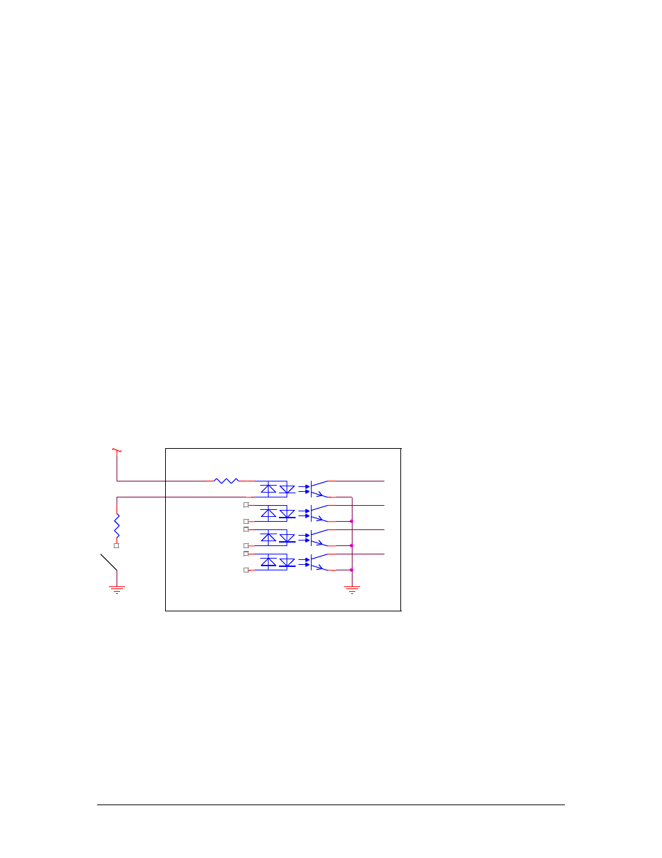
The opto-coupled inputs should be connected as shown in Figure 6. The value of R1 must be
calculated to limit the current flowing through the LED to approximately 15mA. R1 may not
necessary if the internal resistor R3 limits the current enough.
35
INRx
INDx
R3
1K
2
1
3
4
8
7
6
5
16
15
14
13
12
11
10
9
OC2
CNC7H001
Users Supply
R1
2246
Users Gnd
S1
Figure 6
Advertising