SoundTraxx LC Series Owners Manual User Manual
Page 11
LC SERIES DIGITAL SOUND DECODER OWNER’S MANUAL
11
Disconnect all wires leading to both motor terminals. Note that some motor brush connections
are made using a spring contact to the chassis. In such cases, it will be necessary to remove or
modify the spring contact as well. Be aware that some locomotives may make contact between
the motor and frame only when the body is reinstalled.
Next, verify that each motor terminal is electrically isolated from the left and right rail pickups
using an ohm-meter or continuity tester. With your meter set to the ohms scale, touch both meter
probes together and note that the meter indicates 0 ohms (short circuit). You don’t want to see
this indication again! Touch one of the probes to one of the motor brush terminals. Touch the
other probe to the locomotive frame, then the left rail power pickup wire, and finally to the right
rail power pickup wire. Move the first probe to the other motor brush terminal and repeat the
tests. If all tests indicate an open circuit, the motor is properly isolated. Do not proceed further
until this is done.
You will also need to disconnect the wires leading to any lights you wish to use. Using an ohm-
meter, check that each lamp lead is electrically isolated from the frame as well as the left and
right rail pickups.
Step 5. Modify the Tender Body or Locomotive Shell
In the case of a steam locomotive, you will probably be mounting the speaker facing down on the
tender floor or facing up in the coalbunker. On a diesel model, the speaker is likely to be mount-
ed facing down inside the fuel tank, under the fan grilles or inside the cab. In any event, a certain
amount of “body work” may be necessary to accommodate the speaker and decoder. This may
include removing weights, mounting brackets, internal bracing and other structural features.
You will probably need to cut an opening in the body shell for the speaker. A series of small holes
can be easily drilled and will work as well as one large hole provided the open area is at least
one half the area of the speaker cone. In either case, there should be no openings outside or
larger than the speaker cone itself.
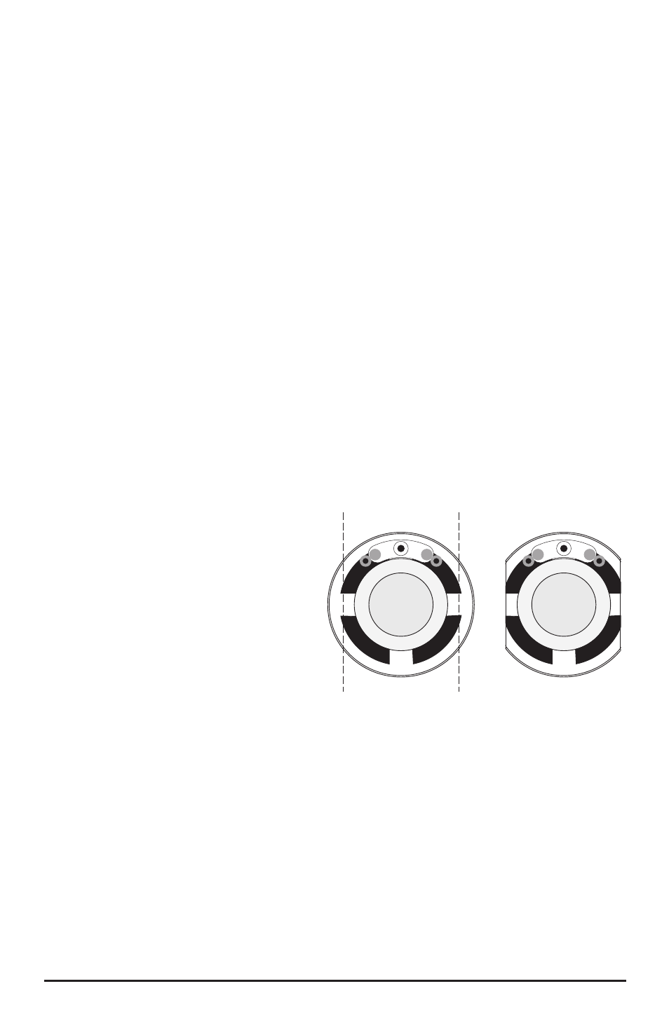
Step 6. Fit the Speaker
If the speaker is wider than the space
in which you intend to install it, it will be
necessary to reduce the speaker width to
get a proper fit. Determine how much the
speaker must be cut down and remove
half of that amount from each side of the
speaker. If the speaker width must be
substantially reduced (i.e., requires cutting
into the speaker diaphragm), you may
find it easier to simply purchase a smaller
speaker – SoundTraxx has a variety of
speakers available to suit your needs.
Otherwise, speakers with plastic frames may be trimmed down using a sharp flat file. Speakers
with metal frames can be quickly trimmed down using a Dremel or similar tool with an abrasive
cut-off wheel. Be sure to wear safety glasses.
As you file or cut down the speaker sides, work slowly and alternate from side to side until the
speaker just fits within the body shell. Be careful to remove only the speaker frame and avoid
cutting into the diaphragm itself.
Step 7. Secure the Speaker in Place
Once bodywork is complete and the speaker has been fitted in place, it must be secured tightly
to the enclosure. For the best sound, an airtight seal is needed around the speaker edge. We
have found the best way to hold the speaker in place is to use silicone RTV - it provides the
airtight seal needed and unlike epoxy or other hard glues, allows the speaker to be readily
Cut equal amounts
from each side.
Figure 8 - Trimming Speaker Cones