SoundTraxx LC Series Owners Manual User Manual
Page 16
LC SERIES DIGITAL SOUND DECODER OWNER’S MANUAL
16
On the other hand, some CVs use individual bits to control different features. This allows up to
eight individual features to be controlled by a single CV and is done to conserve the number of
CVs. As the bit variables can take on only one of two values 0 and 1 they are usually used for
simple variables that are either On or Off, enabled or disabled or something similar. Unfortu-
nately, bit variables are difficult to represent in any form other than binary and still preserve any
meaning. Because most DCC system user interfaces don’t use binary representation, these
numbers are the most difficult to work with and require a tedious series of additions to convert to
the decimal or hex form used by most systems.
Whenever possible, we have tried to use the decimal number system in this manual when
describing the proper values to program into a given CV. Throughout this manual, a hex number
can be distinguished from a decimal number by noting a
0x prefix. Thus 0x10 is the hex version
of sixteen and not ten as one might guess. Binary numbers are represented using a
‘b’ suffix.
100b is really the number four and not one hundred.
To further assist the math-impaired, we have provided a handy-dandy conversion table in Ap-
pendix A that allows one to quickly convert between decimal, hex and binary.
When working with individual bits such as in CV 29, we suggest the following procedure for
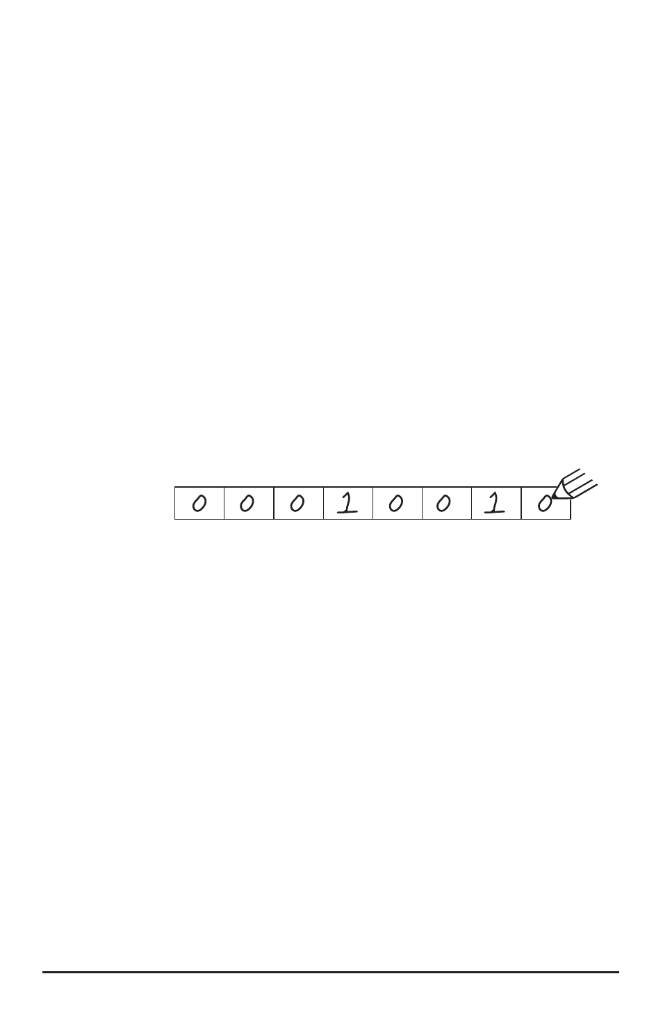
determining the correct value to program. Referring to the CV description, write down from left to
right the value desired for each individual bit. Consider for example, the case of CV 29. We would
like to set this CV so that speed tables are enabled and the 28 speed step mode is in effect.
Referring to the
LC Series Decoder Technical Reference, we see that bit 4 and bit 1 should be
set to 1 and all other bits are cleared to zero. Starting with bit 7 and working to the right, we write
down the individual bit values and get:
We then look up the binary value 00010010b in Appendix A and see that it corresponds to the
decimal value 18 (0x12 in hex). This is the value to use when programming the CV.
Programming Methods
There are two methods for changing the DSD-LC’s CVs:
Service Mode Programming - This programming mode usually requires the loco-
motive to be placed on a special programming track or connected to a dedicated
programmer. The DSD-LC is an advanced decoder and supports four types of service
mode instructions:
Address Mode - Can change CV 1 (Primary Address) only.
Register Mode - Can change CVs 1,2,3,4,7,8 and 29 only.
Paged Mode - Uses a page register to indirectly modify any CV.
Direct Mode - Can directly change any CV.
Operations Mode Programming - Sometimes called ‘Ops Mode’ or ‘Programming on
the Main’, this programming mode allows the CVs to be changed while the locomotive
is operating on the layout even when other locomotives are present. The neat thing
about this mode is that the CVs can be changed in the middle of operation allow-
ing the engineer for example, to increase the momentum rate of a locomotive after it
couples to a train. The main disadvantage of operations mode programming is that the
CV data cannot be read back to verify its value.
Note: The DSD-LC imposes the restriction that CV 1 cannot be changed in this mode
to prevent accidental modification of the locomotive’s address during operation.
bit 7 bit 6 bit 5 bit 4 bit 3 bit 2 bit 1 bit 0