SoundTraxx LC Series Owners Manual User Manual
Page 12
LC SERIES DIGITAL SOUND DECODER OWNER’S MANUAL
12
removed in the future. Be careful that you don’t get any RTV onto the speaker diaphragm as this
will severely distort the sound quality!
Step 8. Install and Wire the Decoder
Note: the following instructions are provided as a general guideline. Refer to the installation and
wiring instructions that came with your decoder for specific information.
Begin by securing the decoder in place using double-sided foam tape. Temporarily refit the body
shell to ensure that adequate clearance still exists.
When wiring the decoder, trim all wires to reduce unnecessary lead length. This will not only
give your installation a neater appearance but also prevent wires from interfering with the drive
mechanism and getting pinched between the frame and body shell.
To ensure long-term reli-
ability, solder all connec-
tions and insulate with
heat shrinkable tubing
such as SoundTraxx P.N.
810036.
Track Connections
Connect the RED wire to
the right(engineer’s side)
track power pickup and
the BLACK wire to the left
track power pickup
Motor Connections
Connect the ORANGE
wire to the motor’s (+) terminal and the GRAY wire to the motor’s (-) terminal.
Speaker Connections
Important: Some DSD-LCs require a capacitor to be wired
in series with the speaker. Refer to the instruction sheet for
details.
Connect one of the PURPLE wires to the speaker’s (-) ter-
minal. Connect the other PURPLE wire to the speaker’s (+)
terminal. NOTE: Some DSD-LC models may be supplied
with tan-colored speaker leads. Refer to the wiring instruc-
tions provided with your decoder for more information.
On smaller speakers, solder the wires to the outside edges of the solder pads as shown in
Figure 10.
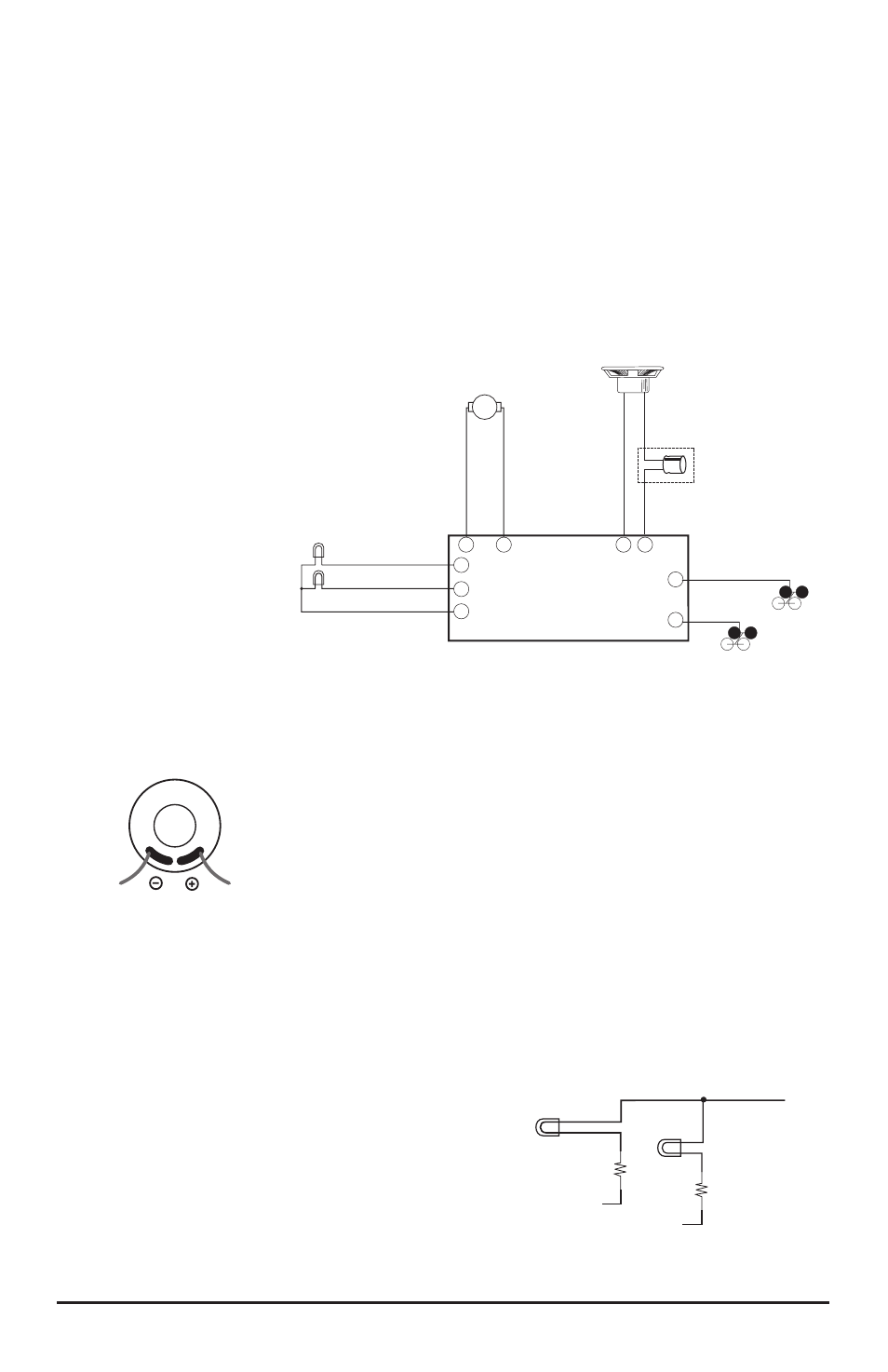
Lighting Connections
12-16V lamps can be directly wired to the function
outputs as shown in Figure 9.
If you are using the DSD-LC to drive 1.5V micro-
bulbs, it will be necessary to wire a small current-
limiting resistor in series with each of the lamps to
prevent them from burning out (see Figure 11). A
separate resistor must be used for each bulb even
if they are connected to the same output. A 560-ohm,
Figure 9 - Wiring Diagram
Gra
y
Red
Black
Orang
e
Speak
er
+
Speak
er
-
-
+
Value varies
with Model
Tan or Purple
Tan or Purple
Headlight
Backup Light
12-16V Lamps
Yellow
White
Blue
2
8
1
9
3
7
4
5
6
Motor
-
Motor
+
Left-hand Rail Pickup
Right-hand Rail Pickup
Figure 10 - Soldering to
Speaker pads (SoundTraxx
3/4” speaker shown)
Forward
Lamp
Reverse
Lamp
560 ohm
Resistor
560 ohm
Resistor
WHITE
YELLOW
FUNCTION COMMON
BLUE
1.5V Microbulbs
Figure 11 - 1.5 Volt Microbulb Lighting
Connections