Iii. wiring pixieplus to display device – SP Controls PixiePlus User Manual
Page 6
III. Wiring PixiePlus to Display Device
Installation
Position the clamshell cable assembly at the
display device you wish to control. Wire the
cable assembly to the PixiePlus using a three-
conductor cable (not included). We recom-
mend using 18-, 20-, or 22-gauge stranded
copper wire cable, such as standard audio
cable (Belden. 8451 or 9451).
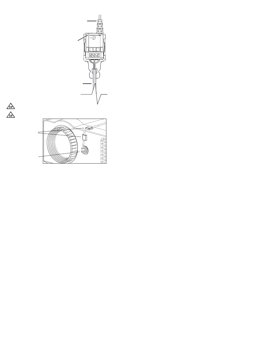
1. Wire Cable Assembly Using the three-con-
ductor cable, wire the cable assembly block to
the corresponding positions on the PixiePlus
captive screw connectors (+6V, GND, BUS).
A two-wire RS232 output splits off from the IR
emitter at the clamshell assembly. For instruc-
tions on wiring and configuring the PixiePlus
with RS232, see documentation for the op-
tional part PXE-PGM-TOOL (required for use
of RS232).
2. Position IR Bud over receiver window of
display device Remove the emitter backing to expose the
adhesive and secure the bud to IR receiver window.
Some devices are extremely sensitive to precise bud
placement.
The IR emitter bud does not illuminate when it sends signal, though the
IR Activity LED will illuminate on the cable assembly clamshell .
3. For a more secure assembly, anchor RS232-IR transmitter clamshell to display
device with included anchors.
4. Affix the IR cable assembly block to the AV display device using the included
double-sided Velcro tape.
5. Connect 6 VDC power supply to IR cable assembly block.
4
POW
ER
6 VDC 300mA
BU
S
Ac
tivity
G
N
D
B
U
S
+6V
3-conductor to
PixiePlus
IR Emitter to IR
Receiver Window
Connect
6V DC
Affix IR emitter to device
with included anchors
Affix bud to IR receiver