Sumix SMX-12A2x User Manual
Page 55
Advertising
External Trigger: Soldering of Connector with Cable
55
SMX-12A2x Series Gigabit Ethernet Camera User Guide
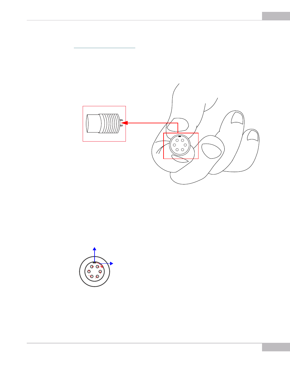
Please note that each pin is marked with a number according to the pin layout (see
). The pins numbering is located at the internal side of the
inner part of the connector.
Figure 7-16 Connector pinout outlook
Note also that direction of pin numbering is done clockwise starting from the key at the
upper edge of the inner part of the connector.
Figure 7-17 The pin numbering direction
When the soldering is done, insert the inner part of the connector in the main part.
1
2
3
4
5
6
1
2
3
4
5
6
Key: the start point of pin num-
bering
Shows the direction of pin
numbering
Advertising