Ttl (jp3) – Sundance SMT395 User Manual
Page 20
Advertising
Version 1.1.7
Page 20 of 26
SMT395 User Manual
Note: The Pin 1 is marked by a white mark on the silkscreen (see white spot on the
previous picture).
TTL (JP3)
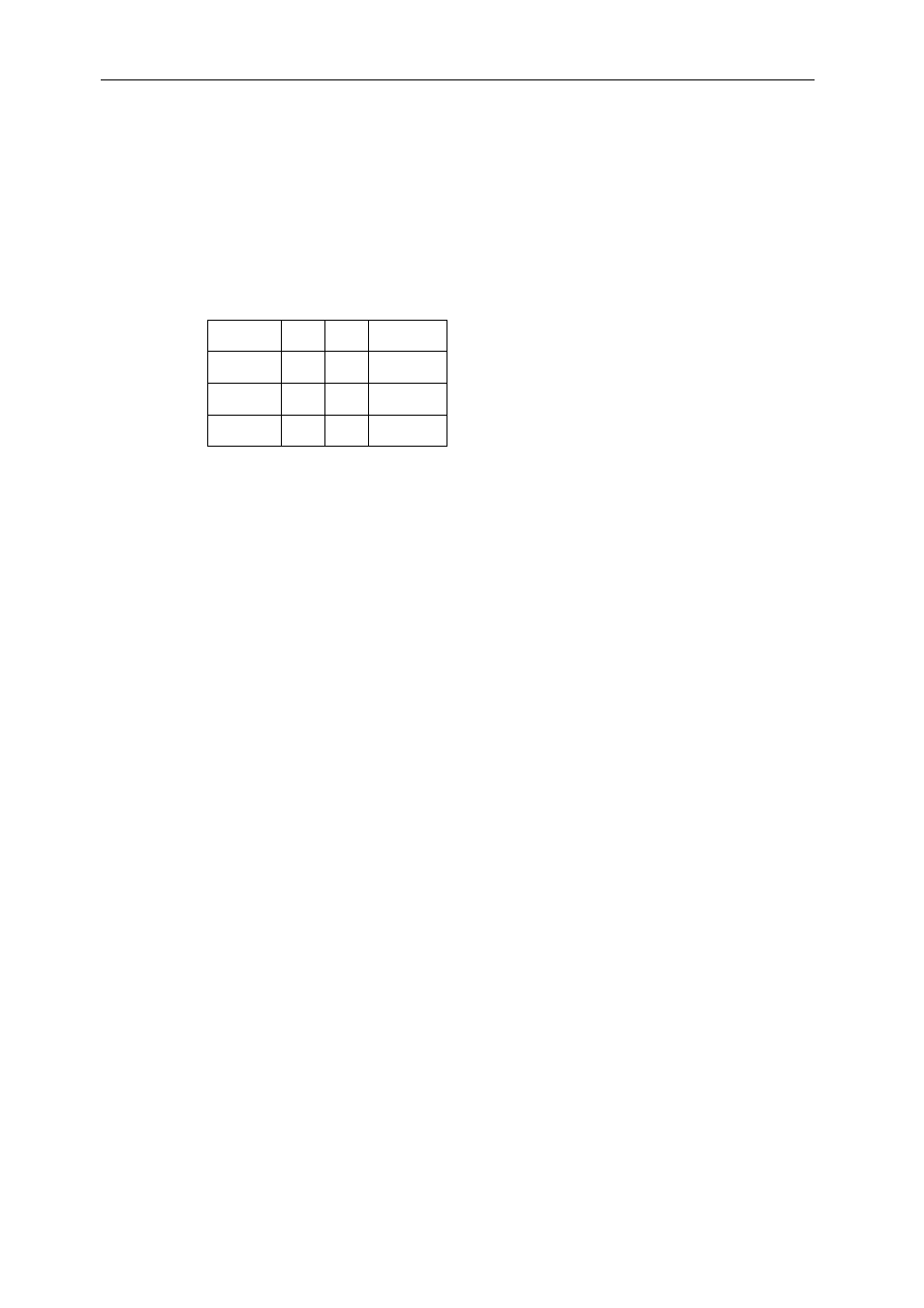
The following shows the pin-outs for JP3 TTL connector:
Signal Pin Pin Signal
V33 1 4 TTL2
TTL0 2 5 TTL3
TTL1 3 6 GND
Note: The Pin 1 is marked by a white mark on the silkscreen (see white spot on the
previous picture).
Advertising