Super systems inc – Super Systems DPC2530 User Manual
Page 6
SSi
Super Systems Inc.
Product Manual #4553 - Model DPC2530 Continuous Dew Point Analyzer
SSi Manual 4553 – DPC2530
Super Systems, Inc.
Page # 6 of 17
Revision Level “E”
(800
) 666-4330
R.H., and the other is 75.3% R.H. These two specific calibration points are already pre-
programmed into the microprocessor board.
1.0 Open the unit.
1.1 Undo the latches on the side of the enclosure.
2.0 Locate the key components within the unit.
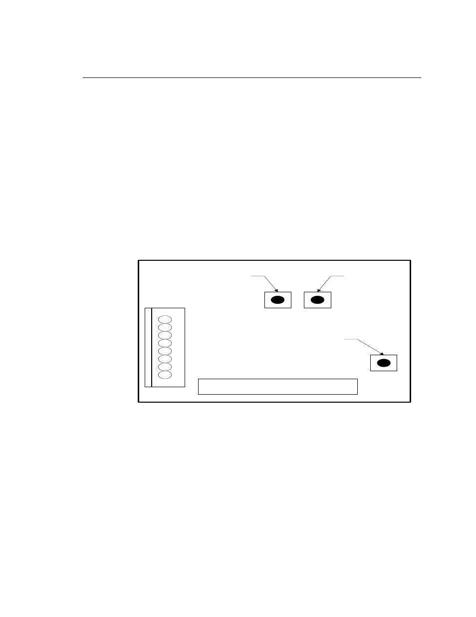
2.1 The microprocessor board is located in the front right side of the unit.
This board contains three very small buttons that are used for calibration.
Two are next to one another, and they are marked “75.3%” and “11.3%”,
while the other has no label. The unmarked button is the “Calibrate” button.
The approximate locations of each button are shown on this diagram:
2.2 The sensor-sampling chamber is located in the bottom left of the unit. It
is the gray rectangular box with brass barb fittings on either side and a black
plastic gland protruding from the center.
2.3 The sensor probe is positioned in the sensor sampling chamber. It is held
in place by the nut on the black plastic gland.
3.0 Remove the sensor probe from the sensor-sampling chamber.
3.1 Loosen the black plastic gland nut and slowly slide the sensor probe out
through the airtight seal. Care must be taken when removing this sensor probe,
since the tip is very delicate and can be easily damaged if it is mishandled.
SPAN
BUTTON
(75.3)
ZERO
BUTTON
(11.3)
CAL
BUTTON
Dew Point Microprocessor Board