TE Technology TC-24-10 User Manual
Page 17
17
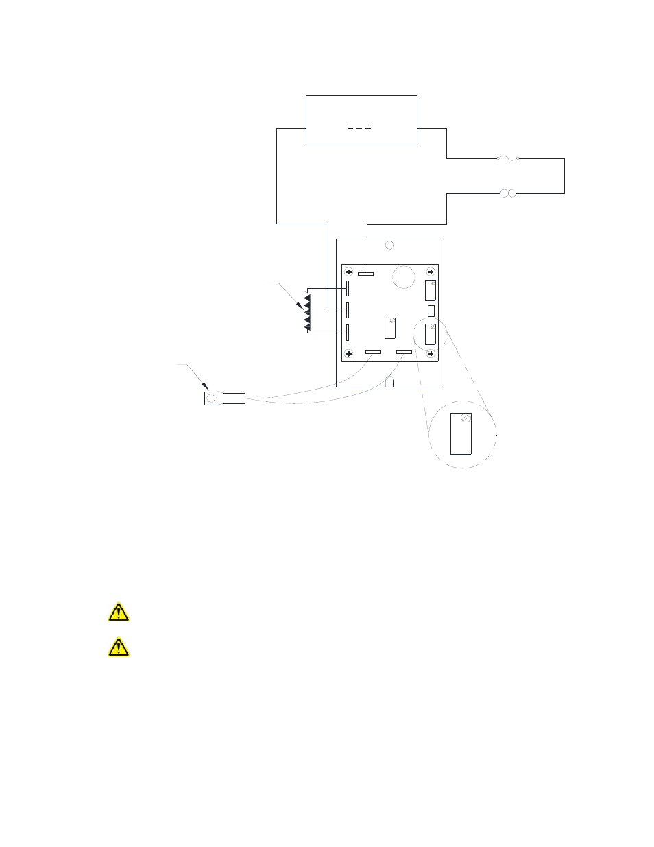
Controller Wiring Diagram (One Power Supply Setup)
Notes: R2 = Proportional bandwidth adjustment (0.5 to 5 °C), clockwise to increase
R7 = Set‐point temperature adjustment (‐20 to +100 °C), clockwise to increase
R8 = Integral rate adjustment (0 to 2.55 repeats per minute), clockwise to increase
All potentiometers have a 25‐turn adjustment range.
WP1, WP2, WP3, WP4, WP5 and WP6 are 0.25 inch quick‐connect terminals
When one or more external fans are used on the TE device, these should be wired directly to a fixed
voltage power supply for constant operation.
When connecting the controller to a TE Technology Thermoelectric Cooling Assembly (TCA) verify that
the electrical jumpers (shorts) located on the TCA terminal block are installed/removed per the TCA
operating manual before powering the controller.
THERMISTOR
TE DEVICE
(shown in cooling mode)
POTENTIOMETER
PIN IDENTIFICATION
DC
POWER SUPPLY
(+)
(-)
(+)
(-)
WP1
WP5
WP6
WP2
WP4
WP3
R8
R7
JP1
R2
1
2
3
=9 V, =26 V, 10 A maximum
FUSE
THERMOSTAT AND
OTHER PROTECTIVE
DEVICES