TE Technology TC-36-25-RS232 User Manual
Page 14
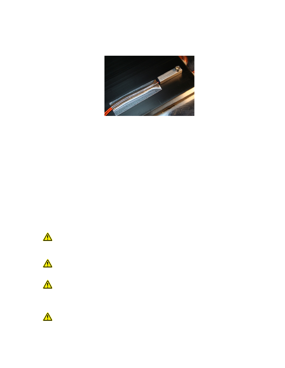
NOTE: When possible, it is recommended that at least 50 mm of the thermistor’s wire be thermally connected to
the cold side of the TE device. This can be accomplished by placing aluminum tape over the thermistor wires and
adhering the wires and tape to the cold side of the cooler. If this is not done, the thermistor wires will be at a
different temperature than the cold side and they will add or remove heat in the region of the thermistor, making
the temperature reading significantly less accurate and thermal response time slower.
The standard thermistor supplied with the TC-36-25 RS232 is the MP-3193. Appendix D “Thermistor Styles for TC-
36-25 RS232” shows dimensional data on the MP-3193 and other thermistor styles readily available as well as the
corresponding temperature-resistance data. If you are using the MP-3193, it is recommended that you use
thermal grease (such as TE Technology TP-1) between the thermistor and the surface to which it is mounted.
See also section 2.8 for further details on using thermistors with different resistance-temperature curves than the
standard thermistor.
1.3
Connect the thermistor wire leads to terminals JP2-5 and JP2-6. The thermistor is non-polarized, so it does not
matter which particular lead goes to which terminal. (See “Controller Wiring Diagram” for reference. The
thermistor is indicated in the diagram as the ‘primary thermistor’.) You can lengthen the wire leads if necessary.
The gauge of the wire is generally not important since the resistance of the wire is insignificant to the resistance of
the thermistor.
1.4.0 The TC-36-25-RS232 can be used with either one or two separate power supplies, depending primarily on the
nominal operating voltage of the TE device. If the maximum TE device input voltage is less than 12 V, then two
power supplies must be used with the controller. In this case, one power supply is for the TE device, and the other
power supply is for the controller itself (the microprocessor and associated electronics). Of course, just one power
supply can be used for powering both the controller and the TE device provided that the TE device’s nominal
operating voltage is within (12 to 36) V.
When using one power supply for powering the controller and the TE device together, the power supply
input voltage is passed directly through the controller to the TE device during the "ON" pulse. The user
should choose an input voltage that is required for the TE device and yet is also is also ≥12 V but ≤ 36 V.
The controller could be damaged if it is operated outside this range.
When using two power supplies, the controller input power supply voltage must be ≥12 V but ≤36 V and
provide a minimum of 200 mA current. The TE device power supply input voltage can be ≥0 V but ≤36 V,
but it should be no greater than the rated input voltage for the TE device.
The TE device current rating should be no more than 25 A at the supplied input voltage regardless of
whether you are using one power supply or using two independent power supplies. NOTE: the maximum
allowable ambient temperature for the controller is 60 °C. The maximum allowable temperature of the
controller base (underneath the transistor-mounting area) is 90 °C. The controller might need additional
heat sinking, depending on ambient conditions and how much current is being drawn by the TE device.
The controller does have an internal 25 A fuse to limit current (Littelfuse PN: 142.6185.5256). This fuse
provides a degree of protection to the controller. If the fuse needs replacing, be sure to compress the fuse
14